Waste rubber tire cracking and recycling equipment
A technology for recycling equipment and waste rubber, applied in plastic recycling, recycling technology, mechanical material recycling, etc., can solve the problems of reducing tire cracking speed, no steel wire cleaning, affecting rubber processing, etc., to speed up cracking speed and filter speed , The effect of accelerating the cracking efficiency
- Summary
- Abstract
- Description
- Claims
- Application Information
AI Technical Summary
Problems solved by technology
Method used
Image
Examples
Embodiment 1
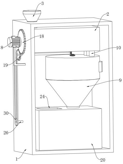
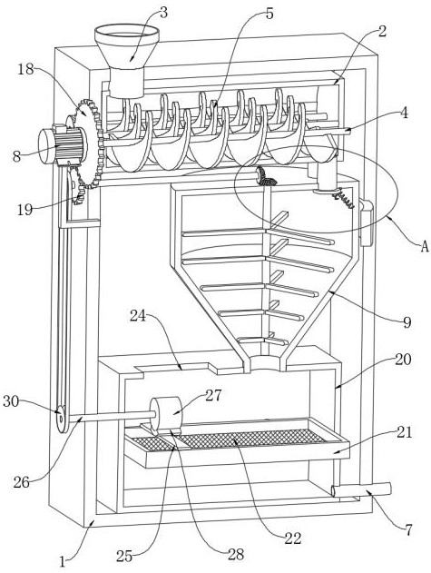
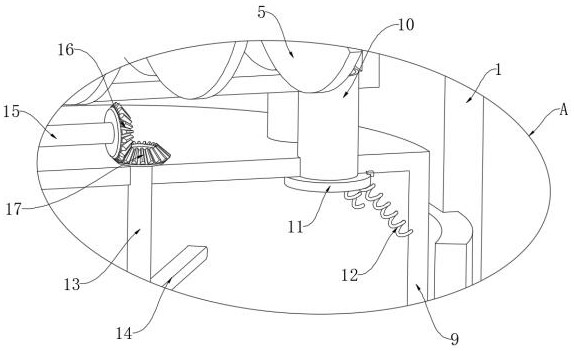
[0030] refer to Figure 1-Figure 6 , a waste rubber tire cracking recovery equipment, including a shell 1, the shell 1 is provided with a crushing mechanism for crushing the tires, the crushing mechanism includes a crushing box 2 fixedly connected above the inner wall of the shell 1, and the crushing mechanism The top of the crushing box 2 is fixedly connected with the feeding pipe 3, the inner wall of the crushing box 2 is rotatably connected with a plurality of rotating shafts 4, and the side walls of the plurality of rotating shafts 4 are fixedly connected with spiral crushing leaves 5, and the gap between two adjacent spiral crushing leaves 5 Arranged in a staggered manner, one end of a plurality of rotating shafts 4 runs through the crushing box 2 and the side wall of the housing 1 respectively and is fixedly connected with a plurality of synchronous wheels 6, which are connected by a synchronous belt, and the side wall of the housing 1 is fixed by a bracket A motor 8 is ...
Embodiment 2
[0044] refer to Figure 7-Figure 8 , different from Embodiment 1, the crushing box 2 is provided with a cleaning mechanism for cleaning rubber, the cleaning mechanism includes a hollow plate 31 fixedly embedded in the top of the crushing box 2, and a plurality of water outlets are provided at the bottom of the hollow plate 31. The hole 32, the side wall of the housing 1 is fixedly connected with two sliding plugs 33, the inner walls of the two sliding plugs 33 are both sealed and slidably connected with a sliding plug 34, and the inner walls of the two sliding plugs 33 are fixedly connected with a one-way water suction pipe 35 , the inner walls of the two sliding plug cylinders 33 are connected with the inner wall of the hollow plate 31 through the one-way outlet pipe 36, the side wall of the housing 1 is provided with a through groove 37, the inner wall of the through groove 37 is slidingly connected with a slide plate 38, and the side wall of the slide plate 38 is passed thro...
Embodiment 3
[0048] refer to Figure 9 , different from Embodiment 1, the side wall of the stirring rod 14 is provided with a chute 41, the inner wall of the chute 41 is slidably connected with a slide bar 42, and the end of the slide bar 42 away from the chute 41 is fixedly connected with a scraper 43, and the scraper 43 The side wall is attached to the inner wall of the cracking cylinder 9 , and the end of the sliding rod 42 away from the scraper 43 is elastically connected to the inner wall of the chute 41 through the second spring 44 .
[0049] In the present embodiment, when a plurality of stirring rods 14 are rotated to stir the tire, at this time, under the action of the second spring 44, the slide bar 42 drives the scraper 43 to be attached to the inner wall of the cracking cylinder 9 all the time, and then the cracking cylinder can be Scrape off the rubber with viscosity on the inner wall of the cracking tube 9 to avoid more rubber sticking to the inner wall of the cracking tube 9...
PUM
 Abstract
Description
Claims
Application Information
 - Generate Ideas
- Intellectual Property
- Life Sciences
- Materials
- Tech Scout
- Unparalleled Data Quality
- Higher Quality Content
- 60% Fewer Hallucinations
Browse by: Latest US Patents, China's latest patents, Technical Efficacy Thesaurus, Application Domain, Technology Topic, Popular Technical Reports.
© 2025 PatSnap. All rights reserved.Legal|Privacy policy|Modern Slavery Act Transparency Statement|Sitemap|About US| Contact US: help@patsnap.com


