
Hydraulic crusher capable of controlling size of crushed particles and protecting hammer bodies

A hydraulic crushing and particle size technology, applied in grain processing and other directions, can solve the problems of inability to intelligently screen the crushed particle size, single function of the crusher, and shortened service life of the crusher.

Pending Publication Date: 2021-11-12
杨单
View PDF0 Cites 0 Cited by
  • Summary
  • Abstract
  • Description
  • Claims
  • Application Information

AI Technical Summary

Problems solved by technology

[0005] Aiming at the deficiencies of the prior art, the present invention provides a hydraulic crusher capable of controlling the size of the crushed particles and protecting the hammer body, capable of screening the crushed materials according to the size of the required crushing particle size, and screening the materials that do not meet the size. Send it to the crushing area again for secondary crushing treatment and when the friction of the hammer body increases, retract the hammer body to protect the hammer body from damage, improve the service life of the crusher, and solve the process of hydraulic crusher for product crushing In the process, the size of the broken particle cannot be intelligently screened, and different crushers need to be selected for different particle sizes, resulting in the single function of the crusher, and the friction during the operation of the crusher will cause damage to the hammer body, which will easily lead to the reduction of the service life of the crusher.

Method used


Image

  • Hydraulic crusher capable of controlling size of crushed particles and protecting hammer bodies
  • Hydraulic crusher capable of controlling size of crushed particles and protecting hammer bodies
  • Hydraulic crusher capable of controlling size of crushed particles and protecting hammer bodies

Examples


Embodiment Construction

[0024] The following will clearly and completely describe the technical solutions in the embodiments of the present invention with reference to the accompanying drawings in the embodiments of the present invention. Obviously, the described embodiments are only some, not all, embodiments of the present invention. Based on the embodiments of the present invention, all other embodiments obtained by persons of ordinary skill in the art without making creative efforts belong to the protection scope of the present invention.

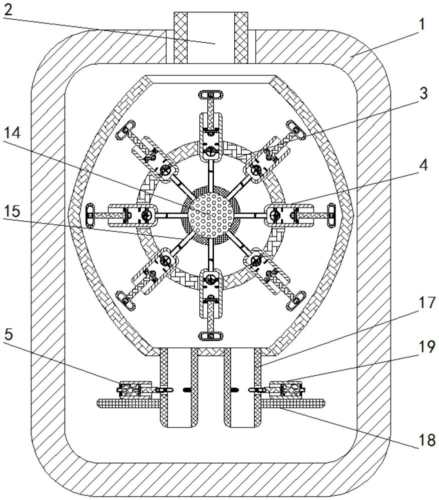
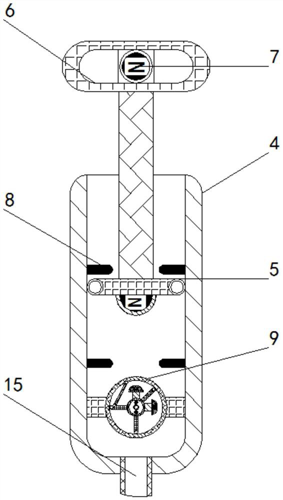
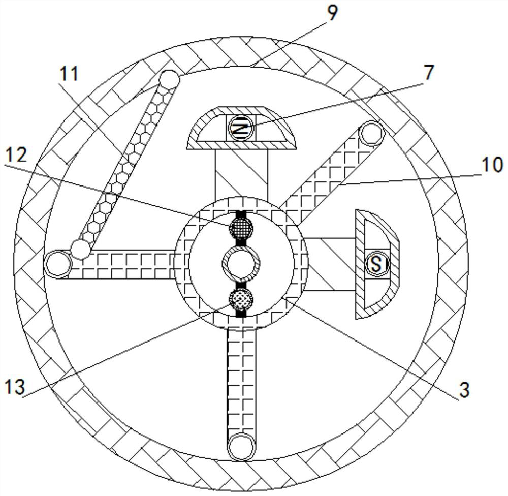
[0025] see Figure 1-5 , a hydraulic crusher capable of controlling the size of crushed particles and protecting the hammer body, comprising a hydraulic crusher main body 1, a feed pipe 2 is fixedly connected to the top of the hydraulic crusher main body 1, and a turntable is movable inside the hydraulic crusher main body 1 3. A telescopic cylinder 4 is fixedly installed on the outer wall of the turntable 3, and a sliding rod 5 is slidably connected to the ins...


PUM


Abstract

The invention relates to the technical field of hydraulic crushers, and discloses a hydraulic crusher capable of controlling the size of crushed particles and protecting hammer bodies. The hydraulic crusher comprises a hydraulic crusher main body, wherein discharging pipes are fixedly mounted in the hydraulic crusher main body, brackets are fixedly mounted on the left side and the right side of the discharging pipes, a hydraulic cylinder is fixedly mounted at the top of each bracket, and a rotating baffle is slidably connected into each hydraulic cylinder. When the particle size of crushed materials conforms to the gaps between the rotating baffles and stop levers, the materials can fall off from the discharging pipes, otherwise, the materials can be left and accumulated at the tops of the rotating baffle in the discharging pipes, and when the hammer bodies rotate to the top of the rotating baffles, magnets in the hammer bodies and magnets in the rotating baffles are opposite in magnetism, the rotating baffles can be attracted to deflect, and the materials accumulated on the rotating baffles can be thrown back to the crushing area to be subjected to secondary crushing, so that the effects of controlling the particle size of the materials and performing secondary crushing on the materials which do not accord with the particle size are achieved.

Description

technical field [0001] The invention relates to the technical field of hydraulic breakers, in particular to a hydraulic breaker capable of controlling the size of broken particles and protecting a hammer body. Background technique [0002] Hydraulic crushers are widely used in mines, smelting, building materials, highways, railways, water conservancy and chemical industries, etc. They have the characteristics of large crushing ratio, uniform product size, simple structure, reliable operation, simple maintenance, and economical operating costs. [0003] In the process of product crushing, the hydraulic crusher cannot intelligently screen the crushing particle size. Different crushers need to be selected for different particle sizes, resulting in a single function of the crusher, and the friction during the operation of the crusher will cause damage to the hammer body, which is easy to break. As a result, the service life of the crusher is reduced, so we propose a hydraulic cr...

Claims


Application Information

Patent Timeline
Patent Type & Authority Applications(China)
IPC IPC(8): B02C13/04B02C13/28B02C13/282B02C13/286B02C13/31
CPCB02C13/04B02C13/28B02C13/282B02C13/286B02C13/31B02C2013/28609
Inventor 杨单
Owner 杨单
Learn More