Photographing system and image processing device
An image processing device and image technology, which is applied in the field of photographic systems, can solve problems such as distortion, and achieve the effect of reducing the impact and suppressing the degradation of image quality
- Summary
- Abstract
- Description
- Claims
- Application Information
AI Technical Summary
Problems solved by technology
Method used
Image

Examples
Embodiment approach 11
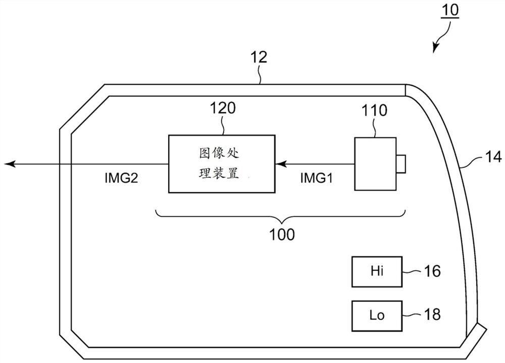
[0064] figure 1 It is a block diagram of the imaging system 100 of Embodiment 1.1. The photography system 100 includes a camera 110 and an image processing device 120 . The camera 110 is built in, for example, the lamp body 12 of a vehicle lamp 10 such as a headlight of an automobile. In addition to the camera 110 , the vehicular lamp 10 includes light sources for the high beam 16 and the low beam 18 , their lighting circuits, a radiator, and the like.
[0065] The camera 110 takes pictures of the front of the camera through the outer lens 14 . In addition to the distortion inherent in the camera 110, the outer lens 14 introduces additional distortion. The type of the camera 110 is not limited, and various cameras such as a visible light camera, an infrared camera, and a TOF camera can be used.
[0066] The image processing device 120 generates information (parameters or functions) necessary for correcting distortion including the influence of the camera 110 and the outer ...
Embodiment approach 12
[0085] Figure 6 It is a block diagram of the imaging system 200 of Embodiment 1.2. The imaging system 200 may also be incorporated in the vehicle lamp 10 as in Embodiment 1.1. The photography system 200 includes a camera 210 and an image processing device 220 . Similar to Embodiment 1.1, the image processing device 220 generates information (parameters or functions) necessary for correcting distortion including the effects of the camera 210 and the outer lens 14 based on the output image IMG1 of the camera 210 . Then, the camera image IMG1 is corrected based on the generated information, and the corrected image IMG2 is output.
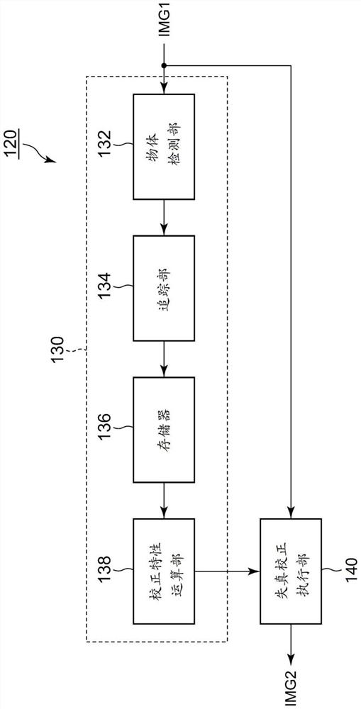
[0086]The image processing device 220 includes a distortion correction execution unit 222 and a correction characteristic acquisition unit 230 . The correction characteristic acquisition unit 230 detects the reference object OBJ whose true shape is known from the camera image IMG1 REF like. Then, based on the real shape S of the image of the refe...
Embodiment approach 2
[0093] (Summary of Embodiment 2)
[0094] One embodiment disclosed in this specification relates to a vehicle imaging system. The photography system includes: a camera; and an image processing device that processes an output image of the camera. When the current frame of the output image contains a foreign object, the image processing device searches out the background image covered by the foreign object from past frames, and pastes the background image on the foreign object area where the foreign object exists in the current frame.
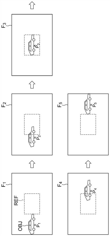
[0095] In an in-vehicle photography system, the camera moves along with the movement of the vehicle, so the image of the object included in the camera image continues to move. On the other hand, when a foreign object is attached, the foreign object tends to stay in the same position continuously, or to move more slowly than the object image. That is, currently, an object image present in a foreign object area covered by a foreign object existed...
PUM
 Abstract
Description
Claims
Application Information
 - Generate Ideas
- Intellectual Property
- Life Sciences
- Materials
- Tech Scout
- Unparalleled Data Quality
- Higher Quality Content
- 60% Fewer Hallucinations
Browse by: Latest US Patents, China's latest patents, Technical Efficacy Thesaurus, Application Domain, Technology Topic, Popular Technical Reports.
© 2025 PatSnap. All rights reserved.Legal|Privacy policy|Modern Slavery Act Transparency Statement|Sitemap|About US| Contact US: help@patsnap.com