Implant for non-luminal area
A technology for implants and regions, applied in the field of implants for non-luminal regions, can solve problems such as the inability to perform the functions of medical devices normally, and achieve the effects of excellent safety, improved corrosion resistance, and fine and uniform particle size
- Summary
- Abstract
- Description
- Claims
- Application Information
AI Technical Summary
Problems solved by technology
Method used
Image
Examples
manufacture example 1 and manufacture example 2
[0122] As materials, high-purity raw metal lumps of Mg, Zn, Mn, and Zr were prepared. These high-purity raw material metal ingots were weighed and put into crucibles so that the respective metals had the component concentrations shown in Table 1, and the melts obtained by melting and stirring at 730°C were cast to produce ingots. , to obtain the magnesium alloys of Production Example 1 and Production Example 2 in which the proportion of the main components is within the scope of the present invention. Rare earth elements and aluminum, which are unavoidable impurities, are not contained in the raw materials used. As the magnesium raw metal block, a magnesium raw material block with a low concentration of impurity Cu and a purity of 99.99% is used, and iron and nickel are removed from the molten metal by performing iron removal treatment in a furnace. The impurity concentration of the sample obtained as described above was measured using an ICP emission spectrometer (manufactur...
manufacture example 3
[0132] As materials, high-purity raw metal lumps of Mg, Zn, Mn, and Zr were prepared. These high-purity raw metal ingots were weighed and put into crucibles so that each metal had the component concentrations described below, and the melts obtained by melting and stirring at 730° C. were cast to produce ingots. Rare earth elements and aluminum, which are unavoidable impurities, are not contained in the raw materials used.
[0133] As the magnesium raw metal block, a magnesium raw metal block with a low concentration of impurity Cu and a purity of 99.9% was used, and iron removal treatment was performed in a furnace to remove iron and nickel from the molten metal.
[0134] The impurity concentration of the obtained ingot was measured using an ICP emission spectrometer (manufactured by Agilent Technologies, Inc., AGILENT 720ICP-OES).
[0135] The component concentration (mass %) of the obtained ingot was as follows, and did not contain aluminum and rare earth.
[0136] The rem...
Embodiment 1
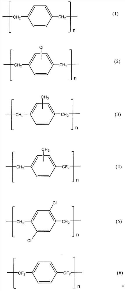
[0149] The mirror-like magnesium alloy substrate A was immersed in a 27M hydrofluoric acid aqueous solution and shaken at 100 rpm. The sample taken out after 24 hours was sufficiently ultrasonically cleaned with water and acetone, and then dried at 60° C. under reduced pressure for 24 hours to obtain a sample in which a magnesium fluoride layer (thickness 1 μm) was formed. A parylene C layer with a thickness of 500 nm was formed on the sample by CVD to obtain a sample having a parylene layer on the magnesium fluoride layer.
PUM
| Property | Measurement | Unit |
|---|---|---|
| thickness | aaaaa | aaaaa |
| thickness | aaaaa | aaaaa |
| yield strength | aaaaa | aaaaa |
Abstract
Description
Claims
Application Information
 - R&D
- Intellectual Property
- Life Sciences
- Materials
- Tech Scout
- Unparalleled Data Quality
- Higher Quality Content
- 60% Fewer Hallucinations
Browse by: Latest US Patents, China's latest patents, Technical Efficacy Thesaurus, Application Domain, Technology Topic, Popular Technical Reports.
© 2025 PatSnap. All rights reserved.Legal|Privacy policy|Modern Slavery Act Transparency Statement|Sitemap|About US| Contact US: help@patsnap.com


