
Strip beam klystron high-frequency structure and resonant cavity characteristic parameter testing and adjusting method thereof

A high-frequency structure and strip technology, which is used in the field of testing and adjusting the high-frequency structure of the strip klystron and its resonant cavity characteristic parameters, can solve the problem of inability to compensate for frequency offset, reduce the quality factor and enhance the electronic injection. Clustering and optimizing the effect of high frequency circuits

Pending Publication Date: 2021-11-09
AEROSPACE INFORMATION RES INST CAS
View PDF0 Cites 0 Cited by
  • Summary
  • Abstract
  • Description
  • Claims
  • Application Information

AI Technical Summary

Problems solved by technology

[0008] The present disclosure provides a method for testing and adjusting the high-frequency structure of the strip-shaped injection klystron and its resonant cavity characteristic parameters, so as to solve the problem that the frequency offset caused by machining errors and brazing deformation cannot be compensated in the above-mentioned background technology. The problem

Method used


Image

  • Strip beam klystron high-frequency structure and resonant cavity characteristic parameter testing and adjusting method thereof
  • Strip beam klystron high-frequency structure and resonant cavity characteristic parameter testing and adjusting method thereof
  • Strip beam klystron high-frequency structure and resonant cavity characteristic parameter testing and adjusting method thereof

Examples


Embodiment Construction

[0072] Hereinafter, embodiments of the present disclosure will be described with reference to the drawings. It should be understood, however, that these descriptions are exemplary only, and are not intended to limit the scope of the present disclosure. In the following detailed description, for purposes of explanation, numerous specific details are set forth in order to provide a thorough understanding of the embodiments of the present disclosure. It may be evident, however, that one or more embodiments may be practiced without these specific details. Also, in the following description, descriptions of well-known structures and techniques are omitted to avoid unnecessarily obscuring the concepts of the present disclosure.

[0073] The terminology used herein is for the purpose of describing particular embodiments only, and is not intended to be limiting of the present disclosure. The terms "comprising", "comprising", etc. used herein indicate the presence of stated features,...


PUM


Abstract

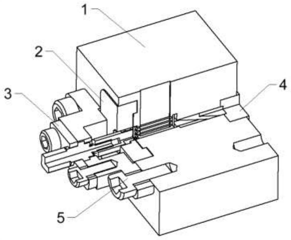
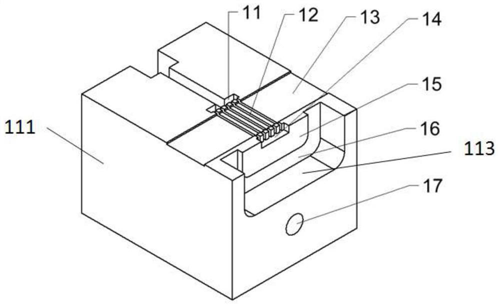
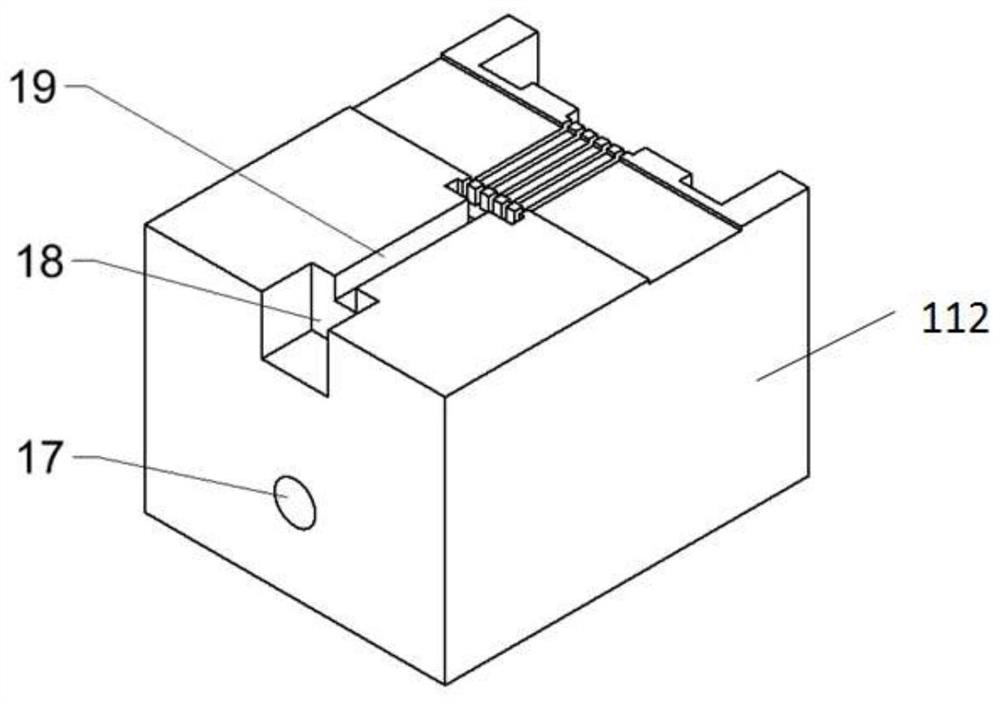
The invention relates to a strip beam klystron high-frequency structure and resonant cavity characteristic parameter testing and adjusting method. The strip beam klystron high-frequency structure comprises a main body part which is formed by combining two split parts, each split part is internally provided with at least one group of tuning units, and each tuning unit comprises a drift channel which penetrates through the main body part and extends in the transverse direction; at least one waveguide groove extending in a longitudinal direction within the drift channel; a straight waveguide cavity is formed at the first end of the waveguide groove and is communicated with the waveguide groove; a diaphragm cover plate assembly comprises a diaphragm which is movably mounted at a second end, opposite to the first end, of the waveguide groove; a tuning mechanism assembly is configured to adjust the distance between the diaphragm and the waveguide groove; an attenuation porcelain assembly comprises a base which is arranged on one side, opposite to the waveguide groove, of the straight waveguide cavity, is arranged on the split part and seals the straight waveguide cavity; and an attenuation porcelain body is arranged in the base and is at least partially inserted into the straight waveguide cavity.

Description

technical field [0001] The present disclosure relates to a microwave and millimeter-wave electric vacuum device, in particular to a strip-shaped injection klystron high-frequency structure and a resonant cavity characteristic parameter testing and adjustment method for microwave and millimeter-wave electric vacuum devices. Background technique [0002] The klystron has developed from the initial simple double-cavity klystron to the currently widely used multi-gap and multi-cavity structure scheme. The cavity forms include reentrant cavity, coaxial cavity, dumbbell-shaped cavity, extended interaction cavity, filter Loading multi-gap cavities, etc., adapting to this, the working mode can be selected from basic mode or high-order mode, and the electronic injection form involves single injection, multiple injection, hollow injection and strip injection schemes. [0003] The klystron can generate high-frequency pulse or continuous wave power output, and because the electron gun, ...

Claims


Application Information

Patent Timeline
Patent Type & Authority Applications(China)
IPC IPC(8): H01J23/20H01J25/10
CPCH01J25/10H01J23/20
Inventor 赵鼎侯筱琬赵超顾伟
Owner AEROSPACE INFORMATION RES INST CAS
Learn More