
Efficient sodium steam cold trap recovery device and method

A recovery device and sodium vapor technology, which is applied in steam/steam condensers, damage protection, lighting and heating equipment, etc., can solve the problems of large equipment volume, low regeneration efficiency, and large heat loss, and achieve increased condensation paths and replacement Thermal area, increased regeneration rate, and faster heating rate

Pending Publication Date: 2021-11-09
XIAN THERMAL POWER RES INST CO LTD
View PDF1 Cites 0 Cited by
  • Summary
  • Abstract
  • Description
  • Claims
  • Application Information

AI Technical Summary

Problems solved by technology

[0002] The top of the primary loop gas chamber of a sodium-cooled fast reactor is covered with argon (Ar) to isolate metallic sodium from air. During the operation of the reactor, the temperature is as high as 353°C, and there is inevitably a large amount of metallic sodium in the primary loop covering gas argon (Ar). Steam will bring great difficulties to the purification or replacement of argon (Ar) in the primary circuit
[0003] The current sodium vapor cold traps for instruments use natural cooling, which has a limited ability to condense sodium vapor and cannot meet the purpose of condensing and collecting sodium vapor under industrial large flow conditions.
In the patent with the application number CN200610140531.6, the sandwich heat exchange structure is used and the heat exchange wire is wound on the outside. The heat exchange area of ​​the sandwich heat exchange structure is small. Under the condition of a certain flow rate of sodium vapor, the required equipment volume is relatively large; In the process of system preheating and regeneration, because the electric heating wire is on the outer wall of the container, it is restricted by the huge thermal resistance of the inner and outer casings and the interlayer air cavity, so the heating rate is slow, the heat loss is large, and the regeneration efficiency is low

Method used


Image

  • Efficient sodium steam cold trap recovery device and method

Examples


Embodiment Construction

[0027] In order to enable those skilled in the art to better understand the solutions of the present invention, the following will clearly and completely describe the technical solutions in the embodiments of the present invention in conjunction with the drawings in the embodiments of the present invention. Obviously, the described embodiments are only The embodiments are a part of the present invention, not all embodiments, and are not intended to limit the scope of the present invention. Also, in the following description, descriptions of well-known structures and techniques are omitted to avoid unnecessarily obscuring the concepts disclosed in the present invention. Based on the embodiments of the present invention, all other embodiments obtained by persons of ordinary skill in the art without making creative efforts shall fall within the protection scope of the present invention.

[0028] The schematic diagrams of the structures according to the disclosed embodiments of th...


PUM


Abstract

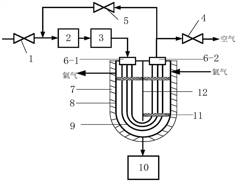
The invention discloses an efficient sodium steam cold trap recovery device and method. A heat exchange tube bundle is located in a heat exchanger, an inlet pipeline communicates with an inlet of an air distributor through an inlet valve, a fan and an electric heater, an outlet of the air distributor communicates with an inlet of the heat exchange tube bundle, and an outlet of the heat exchange tube bundle communicates with an inlet of an air converging device; an outlet of the air converging device is divided into two paths, one path communicates with the outside atmosphere through an outlet valve, and the other path communicates with a pipeline between the inlet valve and the fan through a recirculation valve; the upper side in the heat exchanger is divided into two areas with the bottoms communicating with each other through a heat exchanger partition plate to form an argon flow channel; a plurality of fine mechanical filters are mounted in the argon flow channel; and a sodium collector communicates with a bottom outlet of the heat exchanger. The efficient sodium steam cold trap recovery device and method have the characteristics of large heat exchange area, high temperature rise rate, small heat loss and high regeneration efficiency.

Description

technical field [0001] The invention belongs to the field of sodium-cooled fast reactor sodium vapor cold trap and recovery, and in particular relates to a high-efficiency sodium vapor cold trap recovery device and method. Background technique [0002] The top of the primary loop gas chamber of a sodium-cooled fast reactor is covered with argon (Ar) to isolate metallic sodium from air. During the operation of the reactor, the temperature is as high as 353°C, and there is inevitably a large amount of metallic sodium in the primary loop covering gas argon (Ar). Steam will bring great difficulties to the purification or replacement of argon (Ar) in the primary circuit. [0003] The current sodium vapor cold traps for instruments use natural cooling and have limited ability to condense sodium vapor, which cannot meet the purpose of condensing and collecting sodium vapor under industrial large flow conditions. In the patent with the application number CN200610140531.6, the sandw...

Claims


Application Information

Patent Timeline
Patent Type & Authority Applications(China)
IPC IPC(8): F28D7/06F28F19/01F28B9/08F24H9/18
CPCF28D7/06F28F19/01F28B9/08F24H9/1863
Inventor 姚尧余俨康祯武方杰丰德友蒋昊君杨冬常重喜叶林
Owner XIAN THERMAL POWER RES INST CO LTD
Learn More