
Stiffening ring welding device for pressure steel pipe

A welding device and penstock technology, applied in welding equipment, welding equipment, auxiliary devices, etc., can solve the problems of poor quality of welding horizontal stiffening ring fillet welds, affecting the quality of penstocks leaving the factory, inconsistent welding speed of welders, etc. Relative friction, improve the convenience of feeding, and achieve the effect of precise control

Active Publication Date: 2022-07-08
SINOHYDRO BUREAU 6 CO LTD
View PDF7 Cites 0 Cited by
  • Summary
  • Abstract
  • Description
  • Claims
  • Application Information

AI Technical Summary

Problems solved by technology

In the welding process of penstock stiffening ring fillet welds, the conventional construction method needs to set up platforms of different heights according to the situation, which is time-consuming and laborious; in addition, most of the stiffening ring fillet welds are welded by carbon dioxide gas shielded welding, and two people are usually used to control 2 gas The welding machine performs simultaneous welding of the single-pass stiffening ring fillet weld, and often the welding speed of the welders is inconsistent, and the welding level is different, resulting in poor quality of the stiffening ring fillet weld, which affects the quality of the pressure steel pipe when it leaves the factory.
[0003] The application number is 2020204842989, and the name is a device that can realize automatic welding of stiffening rings. It discloses that rolling steel pipes are rolled by a rolling frame, and a welding device is erected on the steel pipes to jack up the steel pipes to realize welding of the stiffening rings. During the rolling process, the rollers pass through friction. The force drives the steel pipe, which is prone to slippage, resulting in poor welding quality

Method used


Image

  • Stiffening ring welding device for pressure steel pipe
  • Stiffening ring welding device for pressure steel pipe
  • Stiffening ring welding device for pressure steel pipe

Examples


Embodiment Construction

[0033] The present invention will be further described in detail below with reference to the accompanying drawings, so that those skilled in the art can implement it with reference to the description.

[0034] It should be understood that terms such as "having", "comprising" and "including" as used herein do not assign the presence or addition of one or more other elements or combinations thereof.

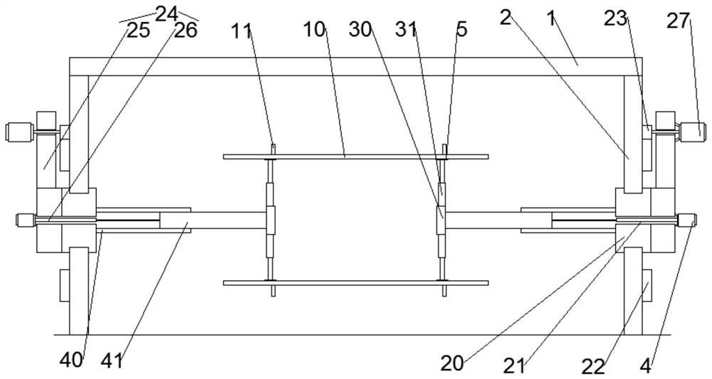
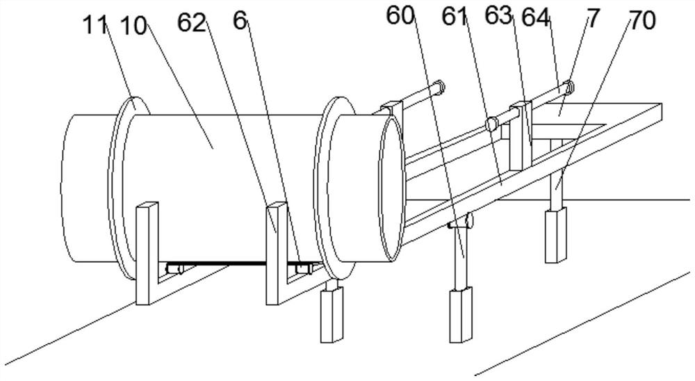
[0035] like figure 1 , 3 As shown, the present invention provides a pressure steel pipe stiffening ring welding device, including a gantry frame 1, a welding device that is telescopically erected on the top of the gantry frame 1, and rolling positioning devices respectively arranged on opposite sides of the gantry frame 1. Each rolling position The device includes:

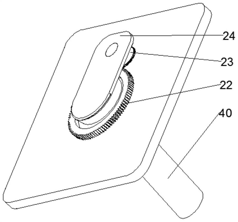
[0036] Mounting plate 2, which is fixed on one side of the gantry 1, and a turntable 20 is rotatably installed on the mounting plate 2, which is used to provide space and position for the installation of rolling asse...


PUM


Abstract

The invention discloses a welding device for a stiffening ring of a pressure steel pipe, comprising a gantry frame, a welding device telescopically erected up and down on the top of the gantry frame, and rolling positioning devices respectively arranged on opposite sides of the gantry frame. Each rolling positioning device includes: a mounting plate , which is fixed on one side of the gantry frame, and a turntable is rotatably installed through the mounting plate; the rolling assembly is located on the outside of the mounting plate, including a large gear fixed on the mounting plate, a pinion gear meshed with the outer circumference of the large gear, an extension plate fixed on the turntable, a rotary motor fixed on the outer surface of the extension plate; a positioning assembly, which includes a telescopic extension fixed on the turntable A rod, a fixed block fixed on the free end of the telescopic rod, and at least three first jacks radiating at equal intervals along the circumference of the fixed block. The invention has the beneficial effects of increasing the rotation effect, reducing the probability of slippage and improving the welding quality on the basis of the labor-saving power source.

Description

technical field [0001] The present invention relates to the technical field of welding equipment. More specifically, the present invention relates to a pressure steel tube stiffening ring welding device. Background technique [0002] In order to achieve the effect of resisting external pressure and increasing the stiffness of the steel pipe for the penstock of the hydropower station, a number of stiffening rings are generally designed on the outer wall of the steel pipe. In the welding process of the stiffened ring fillet weld of the penstock, the conventional construction method needs to set up platforms of different heights according to the situation, which is time-consuming and laborious; in addition, most of the stiffened ring fillet welds are welded by carbon dioxide gas shielded welding, and two people are usually used to control two gas machines. The welding machine performs the simultaneous welding of single-pass stiffening ring fillet welds, and the welding speed o...

Claims


Application Information

Patent Timeline
Patent Type & Authority Patents(China)
IPC IPC(8): B23K31/02B23K37/053
CPCB23K31/02B23K37/0533Y02P70/10
Inventor 叶明任长春何金星岳强林宇赵伟
Owner SINOHYDRO BUREAU 6 CO LTD
Learn More