
Wireless Transceiver Shield for Wireless Networking

A wireless transceiver, wireless network technology, applied in the fields of magnetic field/electric field shielding, cooling/ventilation/heating transformation, electrical components, etc., can solve the mutual interference of signals, the poor anti-interference ability of wireless transceivers, and the inability to expose and repair the wireless transceiver model. and other problems, to achieve the effect of simple and convenient operation, improved practicability and convenient operation

Active Publication Date: 2021-12-10
深圳市诚识科技有限公司
View PDF11 Cites 0 Cited by
  • Summary
  • Abstract
  • Description
  • Claims
  • Application Information

AI Technical Summary

Problems solved by technology

[0002] A wireless transceiver is a device that receives and sends wireless signals. Today, with the development of electronic information technology, it has become popular in people's daily life. Wireless transceivers are widely used in industries such as the Internet of Things, and wireless transceiver modules As the core component of the wireless transceiver, it mainly plays the role of receiving and sending signals, but the traditional wireless transmitting module is prone to signal interference when used, which makes the entire wireless transceiver poor in anti-interference ability.
[0003] The wireless transceiver module in the current wireless transceiver is often directly installed with a metal shielding shell on its surface to prevent the external electric field or magnetic field from interfering with the work of the wireless transceiver module. However, when the wireless transceiver module is overhauled, it is necessary The wireless transceiver module can only be exposed by manually removing the fixing screws, and the wireless transceiver module on the motherboard cannot be quickly exposed for maintenance, thereby reducing the practicability of the wireless transceiver shield; and the shield outside the current wireless transceiver module is in the After the fixing screws are removed, it is often inconvenient for dismantlers to manually remove the metal shielding cover from the outside of the wireless transceiver module, and tools such as tweezers are required to remove the cover, which is very troublesome; at the same time, although the shielding cover used in the current wireless transceiver is close to the The surface of the wireless transceiver module, but the heat dissipation effect of the wireless transceiver module cannot be further improved, thereby reducing the actual use effect of the wireless transceiver shield

Method used


Image

  • Wireless Transceiver Shield for Wireless Networking
  • Wireless Transceiver Shield for Wireless Networking
  • Wireless Transceiver Shield for Wireless Networking

Examples


Embodiment 1

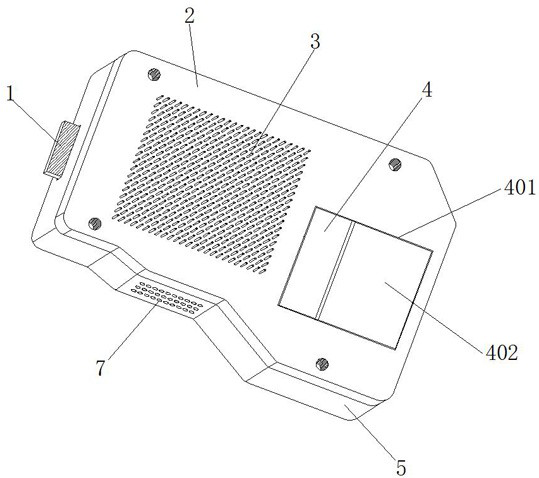
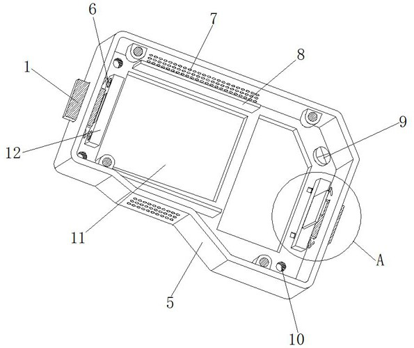
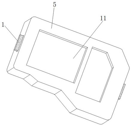
[0037] Example 1, such as Figure 1-5 As shown, when the shielding cover is installed on the main board inside the wireless transceiver, the shielding bin 5 is fixedly installed on the main board inside the wireless transceiver through the cooperation of the fixing bolt 9 and the fixing screw hole 10, and the main board The wireless transceiver module is inserted into the inside of the shielding chamber 5 from the bottom through hole 11, and the wireless transceiver module is completely covered by the cooperation of the shielding chamber 5 and the shielding cover 2, so as to avoid interference to the work of the wireless transceiver module by external electric fields or magnetic fields. When the wireless transceiver module inside the shielding chamber 5 works to generate heat, the heat is transferred to the shield cover 2 and the heat-conducting rod 3 through the heat-conducting plate 15, and the evenly distributed heat-conducting rod 3 can further improve the heat dissipation ...

Embodiment 2

[0038] Example 2, such as Figure 1-8 As shown, when the wireless transceiver module on the main board needs to be overhauled, first open the wireless transceiver housing, and then manually push the push plates 1 on both sides of the shielding chamber 5 to the inside of the shielding chamber 5, and at this time the return spring 6 is pressed The force is elongated and stores the elastic potential energy. At this time, the two groups of mounting blocks 12 move close to each other until the two groups of second clamping blocks 14 leave the interior of the corresponding second card slot 17, thereby releasing the fixing effect on the shielding cover 2. During the moving process of the block 12, the first block 407 on the top of a group of mounting blocks 12 also leaves the inside of the first slot 405 together, which releases the fixing effect on the movable plate 402, and then the maintenance personnel can press the index finger on the movable plate The top of 402 is close to one...


PUM


Abstract

The invention discloses a shielding cover for a wireless transceiver based on a wireless network, which includes a shielding compartment, a shielding cover is arranged on the top of the shielding compartment, and a heat conducting plate is installed on one side of the bottom of the shielding cover, and the top of the shielding cover is close to the side of the heat conducting plate Heat conduction rods are evenly installed on one side, and a bottom through hole is opened on the side of the inner bottom of the shielding chamber close to the heat conduction plate, and push plates are provided on the bottom of both sides of the shielding chamber. The present invention pushes the push plates on both sides of the shielding chamber to the inside of the shielding chamber through the cooperative use of the push plate, the shielding cover, the shielding chamber, the return spring, the second card slot and the spring groove, so that the second clamping block is separated from the second clamping Inside the slot, release the fixing effect on the shielding cover, and then remove the shielding cover from the top of the shielding chamber, exposing the wireless transceiver module in the wireless transceiver shielding cover, which is convenient for maintenance personnel to quickly repair the wireless transceiver module. There is no need to disassemble multiple sets of fixing screws, which greatly improves the practicability of the wireless transceiver shielding cover.

Description

technical field [0001] The invention relates to the technical field of wireless transceivers, in particular to a shielding cover for a wireless transceiver based on a wireless network. Background technique [0002] A wireless transceiver is a device that receives and sends wireless signals. Today, with the development of electronic information technology, it has become popular in people's daily life. Wireless transceivers are widely used in industries such as the Internet of Things, and wireless transceiver modules As the core component of the wireless transceiver, it mainly plays the role of receiving and sending signals, but the traditional wireless transmission module is prone to signal interference when used, which makes the entire wireless transceiver poor in anti-interference ability. [0003] The wireless transceiver module in the current wireless transceiver is often directly installed with a metal shielding shell on its surface to prevent the external electric field...

Claims


Application Information

Patent Timeline
Patent Type & Authority Patents(China)
IPC IPC(8): H05K9/00H05K7/20
Inventor 陈勇
Owner 深圳市诚识科技有限公司
Learn More