


Quick Research
Generate reliable direction feasibility study reports for your R&D in just a few steps.

Technical Q&A
Discover and master advanced knowledge NOW. Basics, ideas, possibilities, all at once.

Find Solutions
As an expert in R&D theories, this can generate solutions to your technical problems instantly.

Evaluate Feasibility
Analyze your overall solution with one click, know your potential R&D risks in advance.

Monitor Landscape
Get weekly tech updates, stay abreast of the latest tech innovations and key insights.
Display module and manufacturing method thereof
A display module and manufacturing method technology, applied in the direction of instruments, identification devices, etc., can solve the problems of display panel cracks, insufficient backplane stiffness, backplane collapse, etc., to prevent cracks or even breakage, improve insufficient stiffness, and enhance Stiffness effect
- Summary
- Abstract
- Description
- Claims
- Application Information
AI Technical Summary
Problems solved by technology
Method used
Image

Examples
Embodiment 1
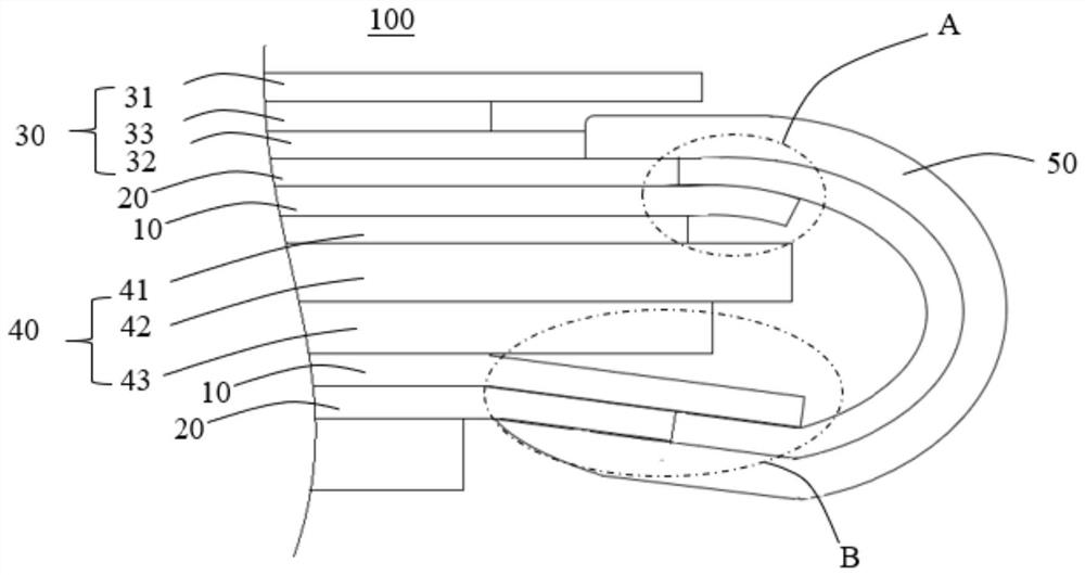
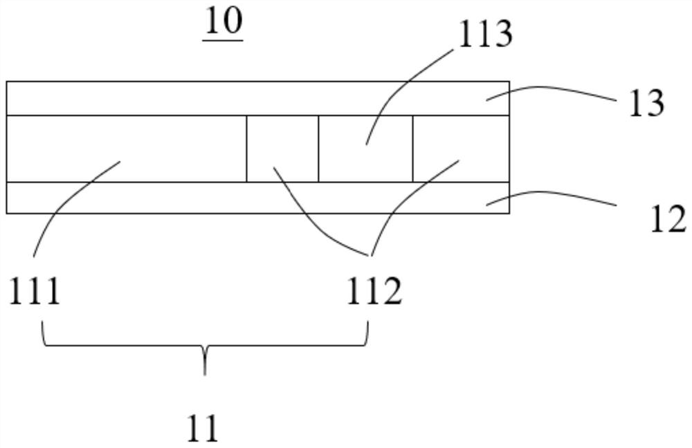
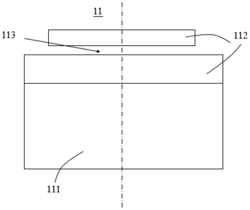
[0044] See figure 2 and image 3, the backplane 10 provided in this embodiment includes a base material 11 , a protective film 12 and a release film 13 . The substrate 11 is sandwiched between the protective film 12 and the release film 13 . The substrate 11 includes a first part 111 and a second part 112 , and the stiffness of the second part 112 is greater than that of the first part 111 . The first part 111 and the second part 112 are spliced to form the base material 11 .
[0045] In this embodiment, the thickness of the first portion 111 is equal to the thickness of the second portion 112 . The first part 111 adopts polyimide (PI), and the material of the second part 112 is selected from polyethylene terephthalate (PET), optical material COP, SRF material, and polyurethane (PU) any of the It can be understood that, in other embodiments, the materials of the first part 111 and the second part 112 can also adopt other configurations, as long as the stiffness require...
Embodiment 2
[0055] See Figure 8 The structure of the backplane 10 provided in this embodiment is substantially the same as the structure of the backplane 10 provided in Embodiment 1, except that the first part 111 and the second part in this embodiment 112 varies in thickness. The thickness of the second portion 112 is greater than that of the first portion 111 , and the material of the first portion 111 is the same as that of the second portion 112 .
[0056] Specifically, in this embodiment, the second portion 112 has a thickness ranging from 70 μm to 100 μm, and the first portion 111 has a thickness ranging from 10 μm to 50 μm.
[0057] Preferably, the thickness of the second part 112 is 90 μm, and the thickness of the first part 111 is 20 μm-40 μm.
[0058] Preferably, the thickness of the second portion 112 may be twice the thickness of the first portion 111 .
[0059] The difference between the structure of the backplane 10 provided in this embodiment and the structure of the ba...
Embodiment 3
[0066] The structure of the backplane 10 provided in this embodiment is substantially the same as the structure of the backplane 10 provided in Embodiment 2, except that the material of the first part 111 is different from that of the second part 112 , the specific diagram can be found in Figure 9 and Figure 10 .
[0067] Specifically, in this embodiment, the first part 111 is made of polyimide (PI), and the material of the second part 112 is selected from polyethylene terephthalate (PET), optical material COP, SRF material, and any one of polyurethane (PU). It can be understood that, in other embodiments, the materials of the first part 111 and the second part 112 can also adopt other configurations, as long as the stiffness requirement is met.
[0068] The structure of the display module 100 provided in this embodiment is substantially the same as that of the display module 100 provided in Embodiment 2, except that the materials of different parts of the backplane 10 ar...
PUM
 Abstract
Description
Claims
Application Information
 - R&D Engineer
- R&D Manager
- IP Professional
- Industry Leading Data Capabilities
- Powerful AI technology
- Patent DNA Extraction
Browse by: Latest US Patents, China's latest patents, Technical Efficacy Thesaurus, Application Domain, Technology Topic, Popular Technical Reports.
© 2024 PatSnap. All rights reserved.Legal|Privacy policy|Modern Slavery Act Transparency Statement|Sitemap|About US| Contact US: help@patsnap.com