Unloading device used for logistics and provided with lifting mechanism and using method of unloading device
A technology of unloading device and logistics, applied in the directions of transportation and packaging, loading/unloading, etc., can solve the problems of low unloading efficiency, single function, and the hoist does not have the function of goods conveying, etc., to improve work efficiency, strong functionality, The effect of reducing the exposed area
- Summary
- Abstract
- Description
- Claims
- Application Information
AI Technical Summary
Problems solved by technology
Method used
Image
Examples
Embodiment 1
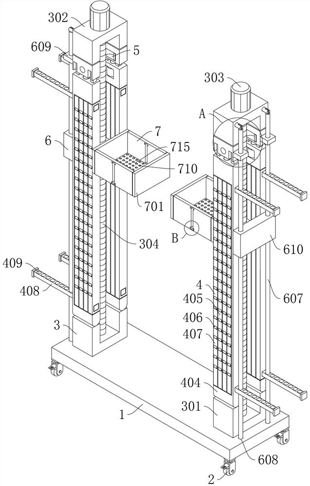
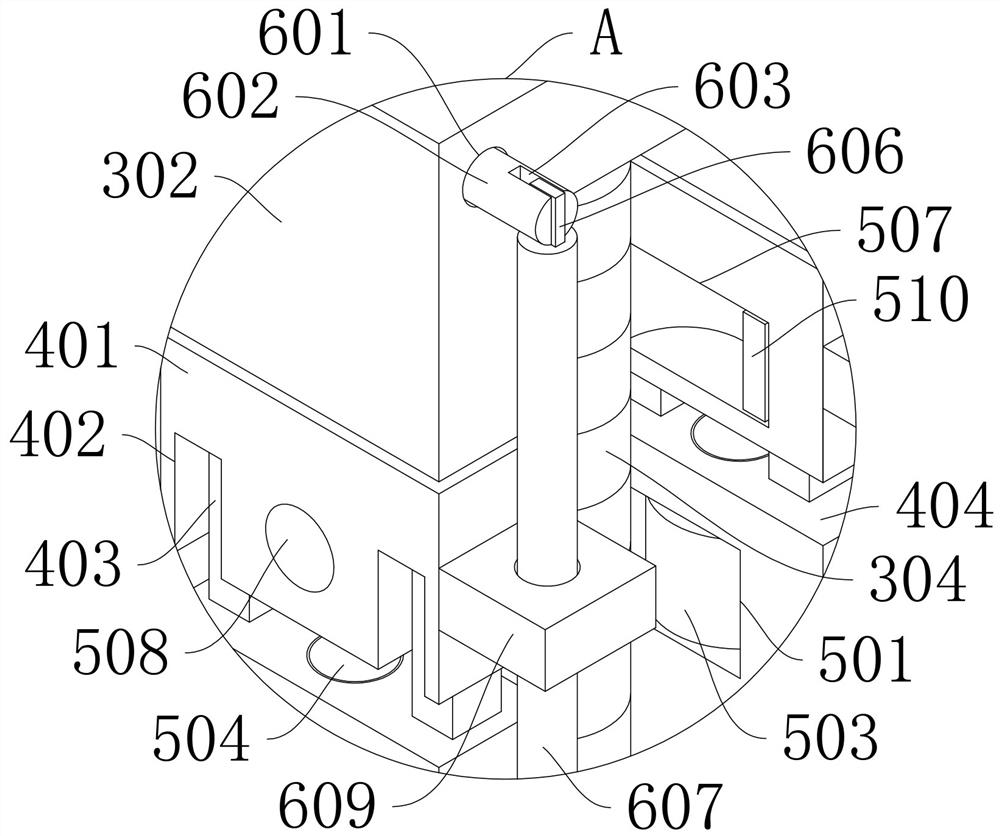
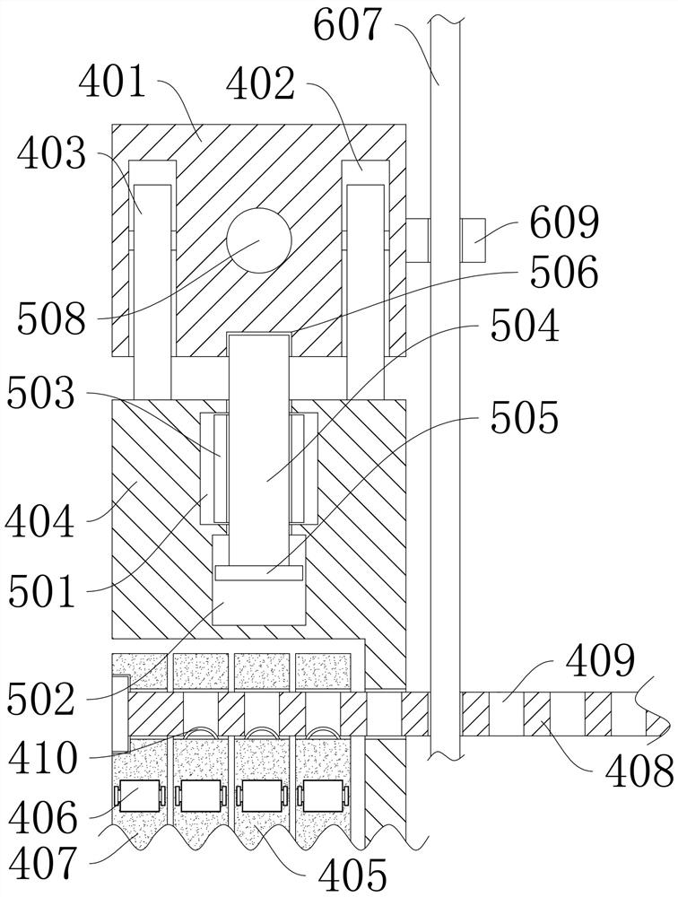
[0051] Such as figure 1 , figure 2 , image 3 with Figure 10 As shown, this embodiment proposes a logistics unloading device with a lifting mechanism, including a base 1, the four corners of the bottom of the base 1 are fixed with universal wheels 2, and both sides of the top of the base 1 are provided with a lifting mechanism 3, The front and rear sides of the lifting mechanism 3 are provided with a transport protection mechanism 4 for transporting goods, and the top end of the transport protection mechanism 4 is provided with a connection limit mechanism 5 for connecting with the lifting mechanism 3, and one side of the lifting mechanism 3 is provided with a locking mechanism for carrying goods. The conveying carrying mechanism 7, one end of the conveying carrying mechanism 7 is provided with a limit mechanism 6 for limiting the rotation of the conveying carrying mechanism 7;
[0052] The conveying protection mechanism 4 can be carried on the lorry after steering, and i...
Embodiment 2
[0056] The scheme in embodiment 1 is further introduced below in conjunction with specific working methods, see the following description for details:
[0057] Such as figure 1 As shown, as a preferred embodiment, on the basis of the above method, further, the lifting mechanism 3 is used to drive the transport protection mechanism 4 to move, and the two lifting mechanisms 3 are respectively arranged on both sides of the top of the base 1. The lifting mechanism 3 includes The bottom frame 301 that is fixedly installed on one side of the top of the base 1, the top of the bottom frame 301 is provided with a top frame 302 positioned at the top of the conveying protection mechanism 4, and a threaded rod 304 is connected between the top frame 302 and the bottom frame 301 through a bearing. The top of 302 is fixedly installed with the driving motor 303 that is used to drive the threaded rod 304 to rotate. By setting the lifting mechanism 3, after the goods enter the inside of the con...
Embodiment 3
[0067] The schemes in Embodiment 1 and Embodiment 2 are further introduced below in conjunction with specific working methods, see the following description for details:
[0068] Specifically, when the logistics unloading device with lifting mechanism is working / using:
[0069] Step 1. Adjust the height: Pull out the limit mechanism 6 from the conveying protection mechanism 4, turn over the conveying protection mechanism 4, after turning over, connect the limit mechanism 5 by operating, fix the conveying protection mechanism 4, and connect the limit mechanism 5 , the conveying protection mechanism 4 can be connected with the lifting mechanism 3, and the height of the conveying protection mechanism 4 can be adjusted by controlling the lifting mechanism 3; the first connecting rod 602 is pulled out from the inside of the first card slot 601, and the second connecting rod is pulled upward 607, pull out the second connecting rod 607 and the inside of the round hole 409, rotate the...
PUM
 Abstract
Description
Claims
Application Information
 - R&D Engineer
- R&D Manager
- IP Professional
- Industry Leading Data Capabilities
- Powerful AI technology
- Patent DNA Extraction
Browse by: Latest US Patents, China's latest patents, Technical Efficacy Thesaurus, Application Domain, Technology Topic, Popular Technical Reports.
© 2024 PatSnap. All rights reserved.Legal|Privacy policy|Modern Slavery Act Transparency Statement|Sitemap|About US| Contact US: help@patsnap.com


