A kind of motor end cover automatic clamping tool and method
A motor end cover and clamping technology, which is used in grinding drive devices, manufacturing tools, metal processing equipment, etc., can solve the problems of grinding processing, complexity, and inability to realize the self-centering processing of motor end covers, and achieves close contact, good stability
- Summary
- Abstract
- Description
- Claims
- Application Information
AI Technical Summary
Problems solved by technology
Method used
Image

Examples
Embodiment 1
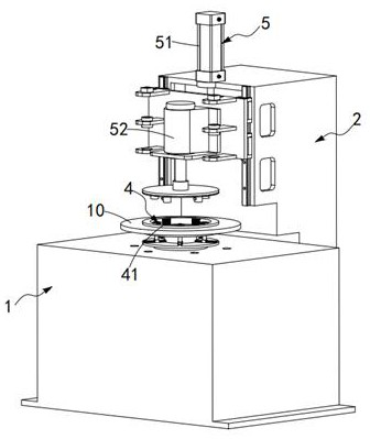
[0055] like Figures 1 to 8 As shown, a motor end cover automatic clamping tool and method, including a processing table 1 and a column 2, the column 2 is adjacent to the processing table 1 side, and also includes:
[0056] A charging tray 3, the charging tray 3 is rotatably mounted on the processing table 1, and the charging tray 3 is used for installing the motor end cover 10;
[0057] A centering assembly 4, the centering assembly 4 is installed on the charging tray 3, and the centering assembly 4 includes a plurality of extended centering rods 41 equidistantly arranged along the circumference of the charging tray 3 , the expansion centering rod 41 is slidably arranged along the radial direction of the charging tray 3 , and the expanding centering rod 41 expands along the radial direction of the charging tray 3 along with the rotation of the charging tray 3 . The inner ring of the motor end cover 10 is in conflict, so that the motor end cover 10 is concentrically arranged ...
Embodiment approach
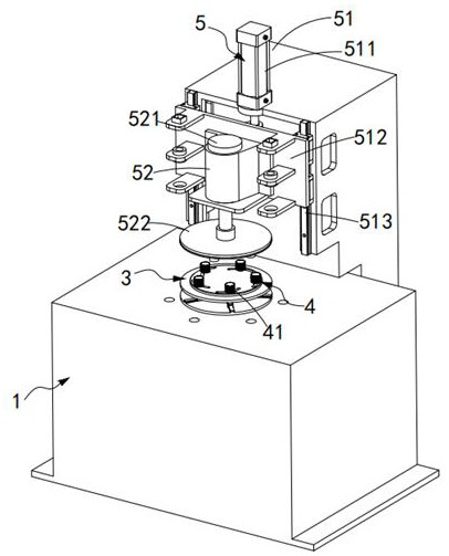
[0069] As a preferred embodiment, the descending assembly 51 includes:
[0070] A hydraulic cylinder 511, the hydraulic cylinder 511 is vertically installed on the top of the column 2, and the hydraulic cylinder 511 pushes down vertically; and
[0071] Lifting plate 512 , said lifting plate 512 is slidably installed on said column 2 through slider pair 513 along the vertical direction, and said lifting plate 512 is fixedly connected with the push rod of said hydraulic cylinder 511 .
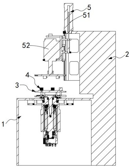
[0072] Wherein, the fixing assembly 52 includes:
[0073] Rotating main shaft 521, described rotating main shaft 521 is vertically installed on the described lifting plate 512, and the lower end of this rotating main shaft 521 is equipped with gland 522, and this gland 522 is used for compressing the top of described motor end cover 10;
[0074] An electromagnet 523, the electromagnet 523 is installed on the lower end surface of the gland 522, and the electromagnet 523 is used to adsorb and fix ...
Embodiment 2
[0084] like Figure 9 As shown, a clamping method based on the motor end cover automatic clamping tooling of embodiment 1 comprises the following steps:
[0085] Step 1, loading the workpiece, set the motor end cover 10 on the loading boss 32 of the loading tray 3 installed on the top of the processing table 1;
[0086] Step 2. Workpiece pre-centering. The electric spindle located below the charging tray 3 drives the charging tray 3 to rotate. The extended centering rod 41 installed on the charging tray 3 expands outwards and conflicts with the inner ring of the motor end cover 10, and the completion Preliminary centering treatment between the motor end cover 10 and the charging tray 3;
[0087] Step 3, top tightening process, after the motor end cover 10 completes the preliminary centering process, the lowering assembly 51 drives the fixing assembly 52 to descend, and the stopper post 524 in the fixing assembly 52 is inserted into the inner ring of the motor end cover 10, an...
PUM
 Abstract
Description
Claims
Application Information
 - R&D
- Intellectual Property
- Life Sciences
- Materials
- Tech Scout
- Unparalleled Data Quality
- Higher Quality Content
- 60% Fewer Hallucinations
Browse by: Latest US Patents, China's latest patents, Technical Efficacy Thesaurus, Application Domain, Technology Topic, Popular Technical Reports.
© 2025 PatSnap. All rights reserved.Legal|Privacy policy|Modern Slavery Act Transparency Statement|Sitemap|About US| Contact US: help@patsnap.com