A processing machine for punching and cutting corners of thin steel

A processing machine and angle cutting technology, applied in the field of thin steel plate manufacturing, can solve problems such as manual adjustment of molds, and achieve the effects of improving fixed position, accurately positioning local stamping deformation, and reducing cumbersomeness

Active Publication Date: 2021-11-26
启东市神龙工业配套有限公司
View PDF10 Cites 0 Cited by
  • Summary
  • Abstract
  • Description
  • Claims
  • Application Information

AI Technical Summary

Problems solved by technology

[0005] The purpose of the present invention is to address the shortcomings of the prior art and provide a thin steel punching and corner cutting machine, which drives the engaging assembly to move downward through the movement of the transmission assembly, and the engaging assembly pulls the fastening assembly through the steering rod The thin steel plate is fixed, and the clamping components are fixed under the counter force of the thin steel plate, so that the opposite side of the thin steel plate is clamped and fixed without affecting the adjacent side, so as to achieve the function of adapting to different sizes of thin steel plates and solve the problem of punching and cutting of thin steel plates. The problem of manually adjusting the mold for different sizes during corner machining

Method used


Image

  • A processing machine for punching and cutting corners of thin steel
  • A processing machine for punching and cutting corners of thin steel
  • A processing machine for punching and cutting corners of thin steel

Examples


Embodiment 1

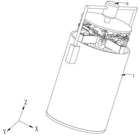
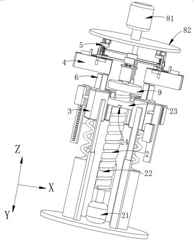
[0077] like Figure 1-2 Shown, a kind of thin steel stamping corner cutting processing machinery, including:

[0078] Stamping cylinder 1;

[0079] The transmission assembly 2 is arranged above the top of the inner wall of the stamping cylinder 1;

[0080] The engaging assembly 3 is slidably connected with the transmission assembly 2;

[0081] Fastening assembly 4, which is arranged on the top of punching cylinder 1 and is connected with transmission assembly 2;

[0082] Stamping component 5, it is arranged on the top of fastening component 4, and is connected with fastening component 4;

[0083] An air pressure component 6, which is connected with the engaging component 3;

[0084] A pressure assembly 7, one end of the pressure assembly 7 is connected to the fastening assembly 4, and the other end is connected to the air pressure assembly 6 through a pressure hose 74;

[0085] When the transmission component 2 drives the engaging component 3 to move downward, it drives t...

Embodiment 2

[0115] like Figure 13 As shown, the components that are the same as or corresponding to those in the first embodiment are marked with the corresponding reference numerals in the first embodiment. For the sake of simplicity, only the differences from the first embodiment will be described below. The difference between this embodiment two and embodiment one is:

[0116] like Figure 13 As shown, preferably, the stamping assembly 5 includes:

[0117] The positioning chute rod 57 is arranged on both sides of the top of the pressure piston 71, and the surface is provided with a through groove 58, and the vertical direction overlaps between adjacent positioning chute rods 57;

[0118] Angle-cut positioning seat 54, which is located above the intersection of two adjacent positioning chute bars 57, and is slidably connected with two adjacent through grooves 58 through a slide bar 59;

[0119] Stamping upper seat 53, which is connected with the top of slide bar 59, is provided with...


PUM


Abstract

The invention provides a punching and corner-cutting processing machine for thin steel materials, which includes a stamping cylinder, and a transmission assembly, which is arranged above the top of the inner wall of the stamping cylinder, and an engaging assembly, which is connected with the bayonet pin provided by the transmission assembly. The transmission component is slidingly connected, and also includes a fastening component, which is set on the top of the punching cylinder. When the thin steel is placed on the unloading platform, the screw motor starts to move at this time, driving the pressure piston to fit the edge of the thin steel. , when it is tightly attached, the air inside the pressure cylinder is squeezed under the reaction force of the thin steel. After the air is squeezed, the curved slider is driven to rotate. At this time, the snap frame is fixed, thereby fixing the side of the thin steel plate , and does not affect the adjacent side to continue to press the side. When the screw slider moves to the bottom and stops, the thin steel plate has been fixed at this time, so as to achieve the function of fixing and locking thin steel plates of different sizes.

Description

technical field [0001] The invention relates to the field of thin steel plate manufacturing, in particular to a punching and corner cutting processing machine for thin steel. Background technique [0002] In today's steel development process, many industrial parts and some large-scale industrial equipment are inseparable from the use of steel. The use of steel can effectively improve the service life of components. At the same time, the hardness of steel is higher and wear-resistant, increasing Therefore, it is necessary to increase the accuracy of positioning and processing when processing thin steel plates in industry. [0003] Chinese patent CN203155795U discloses a thin steel plate punching corner cutting machine, including: a frame; a transmission screw arranged on the frame; at least two molds sleeved on the transmission screw; At least one mold can move axially along the transmission screw; a clutch set is arranged at one end of the mold to link the transmission scre...

Claims


Application Information

Patent Timeline
Patent Type & Authority Patents(China)
IPC IPC(8): B21D28/02B21D43/00
Inventor 施恺
Owner 启东市神龙工业配套有限公司
Why Eureka
Try Eureka