Large antenna capable of realizing overhead tracking function

A tracking function and antenna technology, applied in the direction of antenna, antenna support/mounting device, electrical components, etc., can solve the problems of large overturning moment of antenna, large two-axis moment of inertia, and limited bearing capacity, so as to reduce the overall height and movement Stable and reliable, weight saving effect

Pending Publication Date: 2021-10-29
NO 54 INST OF CHINA ELECTRONICS SCI & TECH GRP
View PDF0 Cites 0 Cited by
  • Summary
  • Abstract
  • Description
  • Claims
  • Application Information

AI Technical Summary

Problems solved by technology

But its disadvantages are: the structure is not compact, and both axes need to add balance weights, resulting in a large moment of inertia of the two axes, which is not suitable for large antennas
But its disadvantages are: 1. The rotation backlash of the tilting mechanism will directly affect the basic stiffness and tracking accuracy of the antenna base, thereby reducing the resonant frequency of the antenna base. Large overturning moment; 3. Limited bearing capacity, difficult to manufacture and adjust, and not suitable for large antennas
[0010] Looking at all the large fully movable antennas in the world today, without exception, they have not solved the problem of overhead tracking

Method used


Image

  • Large antenna capable of realizing overhead tracking function
  • Large antenna capable of realizing overhead tracking function
  • Large antenna capable of realizing overhead tracking function

Examples


Embodiment Construction

[0045] Below, the present invention will be further described in conjunction with the accompanying drawings and specific embodiments.

[0046] In order to illustrate the technical solutions of the embodiments of the present invention more clearly, the accompanying drawings of the embodiments will be briefly introduced below. Obviously, the accompanying drawings in the following description are only some embodiments of the present invention, and those of ordinary skill in the art Generally speaking, other drawings can also be obtained based on these drawings on the premise of not paying creative work.

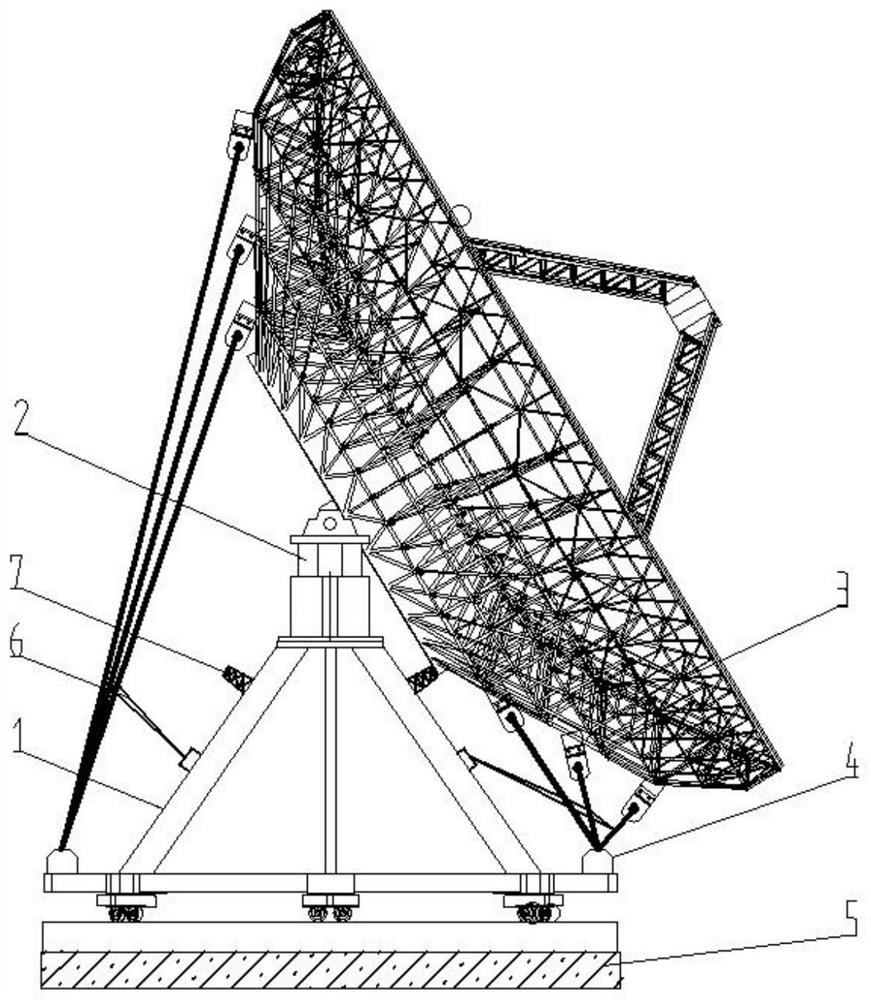
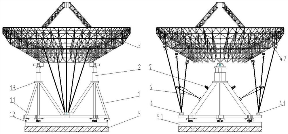
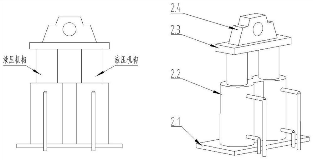
[0047] A large-scale antenna that can realize the function of overhead tracking. On the basis of the traditional azimuth-elevation reflector antenna structure, a tilting mechanism acting on the reflector is added. This enables the antenna not only to realize the conventional azimuth and pitch motions of the antenna mount, but also to increase the tilt motion of the reflector in ...


PUM


Abstract

The invention discloses a large antenna capable of realizing an overhead tracking function, and belongs to the technical field of antennas. The antenna comprises a seat frame, a reflector and an inclination structure, wherein a pitch shaft is arranged at the bottom of the reflector, and the inclination structure is arranged at the top of the seat frame; the upper platform of the inclination structure is provided with a pitch shaft seat used for being matched with the pitch shaft; each inclination group comprises a lifting device; the lifting devices are uniformly arranged at the top of an azimuth chassis; the lifting device comprises two sets of hydraulic servo structures which are backup for each other; and the hydraulic cylinders of the two sets of hydraulic servo structures, which are mutually backed up, are tightly attached and arranged side by side. The inclination group further comprises an upper platform and a lower platform; and the upper platform is located on the piston rod top of the hydraulic cylinder, and the lower platform is located at the bottom of a cylinder barrel of the hydraulic cylinder. The antenna can realize an overhead tracking function, and has the advantages of compact structure and high reliability.

Description

technical field [0001] The invention relates to the technical field of antennas, in particular to a large-scale antenna capable of realizing the overhead tracking function. Background technique [0002] Antennas of satellite ground fixed tracking and measurement stations often use azimuth-elevation antenna mounts. This type of mount has the advantages of simple structure, traditional reliability, and high precision. But it can't solve the problem of overhead tracking. Overhead tracking is a key technique in moving target tracking. Especially for low-orbit satellites, there will be a "blind zone" near the 90° zenith. When the satellite flies through this blind area, the azimuth velocity of the antenna changes sharply while the pitch velocity changes slowly, and the antenna of the ground station will lose the tracking target because the azimuth velocity is not high enough. The size of the "blind zone" is related to the azimuth velocity of the ground station antenna and the...

Claims


Application Information

Patent Timeline
Patent Type & Authority Applications(China)
IPC IPC(8): H01Q3/02H01Q1/12H01Q19/12
CPCH01Q3/02H01Q1/12H01Q19/12
Inventor 曹江涛赵东贺宫玉松孙哲孙立杰杨亚军宋建虎郭云玲郑禄浩陈慧全
Owner NO 54 INST OF CHINA ELECTRONICS SCI & TECH GRP
Why Eureka
Try Eureka