
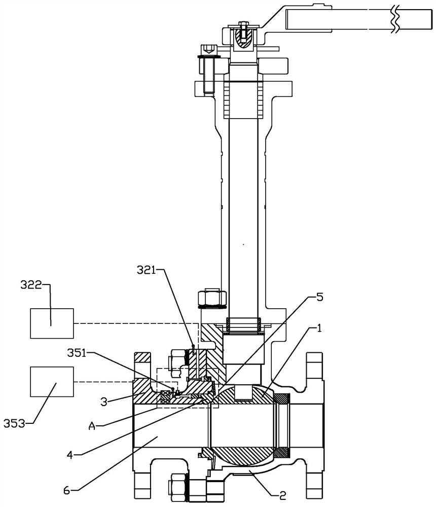
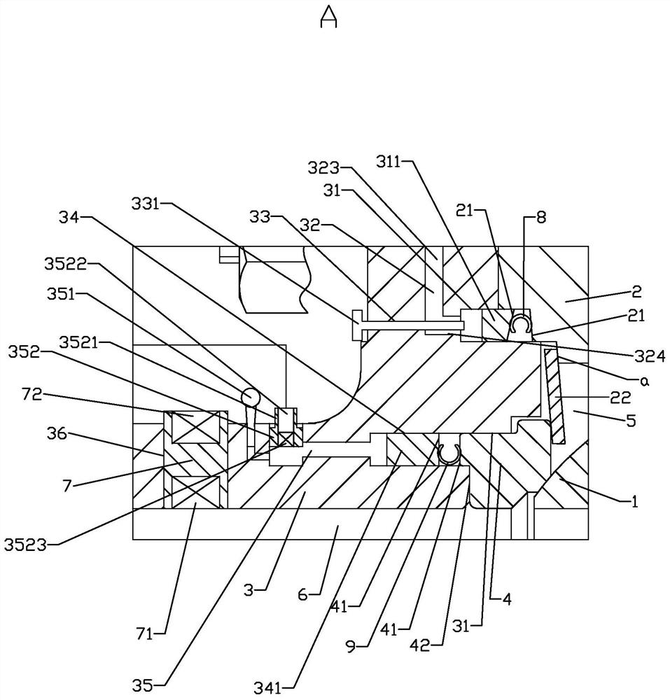
High-temperature hard sealing floating ball valve with manual and automatic adjusting function

A floating ball valve, hard sealing technology, applied in the valve details, valve device, valve shell structure and other directions, can solve the problems affecting the sealing performance of the flow channel, leakage and so on

Pending Publication Date: 2021-10-29
FANGZHENG VALVE GRP
View PDF8 Cites 0 Cited by
  • Summary
  • Abstract
  • Description
  • Claims
  • Application Information

AI Technical Summary

Problems solved by technology

[0002] The high-temperature hard-sealed floating ball valve with manual self-adjustment function is a ball valve used in high-temperature environments and adopts a floating hard-sealed seat. It includes a valve body and a bonnet distributed on the left and right. The cavity of the sphere, the valve body and the valve cover are generally fixed by bolts, and the bolts will be loosened due to various external factors such as pipeline stress and vibration, and the distance between the sealing surfaces between the body and cover will change slightly, so that it is easy to remove from the valve. Leakage in the gap between the valve body and the valve cover affects the sealing of the flow channel. At the same time, there is a difference between the temperature in the flow channel and the temperature outside the valve body, resulting in a difference between the inner and outer thermal expansion and cooling of the valve cover and the valve body. Moreover, The temperature of the working condition also changes during the working process, and the same sealing structure often leads to over-extrusion or under-extrusion of the inner seal and the outer seal.

Method used


Image

  • High-temperature hard sealing floating ball valve with manual and automatic adjusting function
  • High-temperature hard sealing floating ball valve with manual and automatic adjusting function

Examples


Embodiment Construction

[0020] The technical solutions of the present invention will be clearly and completely described below in conjunction with the accompanying drawings. Apparently, the described embodiments are some of the embodiments of the present invention, but not all of them. Based on the embodiments of the present invention, all other embodiments obtained by persons of ordinary skill in the art without making creative efforts belong to the protection scope of the present invention.

[0021] In the description of the present invention, it should be noted that the terms "center", "upper", "lower", "left", "right", "vertical", "horizontal", "inner", "outer" etc. The indicated orientation or positional relationship is based on the orientation or positional relationship shown in the drawings, and is only for the convenience of describing the present invention and simplifying the description, rather than indicating or implying that the referred device or element must have a specific orientation, ...


PUM


Abstract

The invention relates to a high-temperature hard sealing floating ball valve with a manual and automatic adjusting function. The high-temperature hard sealing floating ball valve comprises a ball body, a valve body, a valve deck and a valve seat, the valve body and the valve deck are distributed left and right and fixedly matched, a cavity used for installing the ball body is formed between the valve body and the valve deck, and the valve deck and the valve body are each provided with a flow channel communicating with the cavity. An outer sealing piece is arranged between the valve deck and the valve body, a valve seat installation groove for installing the valve seat is formed in the end face, facing the valve body, of the valve deck, an inner sealing piece is arranged between the valve seat installation groove and the valve seat, an inner temperature sensor is arranged on the inner wall of the flow channel, and an outer temperature sensor is arranged on the outer side of the valve deck. The valve deck is provided with an outer adjusting mechanism for adjusting the deformation degree of the outer sealing piece and an inner adjusting mechanism for adjusting the deformation degree of the inner sealing piece. By the adoption of the scheme, the high-temperature hard sealing floating ball valve capable of prolonging the service life of the sealing pieces and guaranteeing the sealing performance is provided.

Description

technical field [0001] The invention relates to the field of ball valves, in particular to a high-temperature hard-sealed floating ball valve with manual self-adjustment function. Background technique [0002] The high-temperature hard-sealed floating ball valve with manual self-adjustment function is a ball valve used in high-temperature environments and adopts a floating hard-sealed seat. It includes a valve body and a bonnet distributed on the left and right. The cavity of the sphere, the valve body and the valve cover are generally fixed by bolts, and the bolts will be loosened due to various external factors such as pipeline stress and vibration, and the distance between the sealing surfaces between the body and cover will change slightly, so that it is easy to remove from the valve. Leakage in the gap between the valve body and the valve cover affects the sealing of the flow channel. At the same time, there is a difference between the temperature in the flow channel an...

Claims


Application Information

Patent Timeline
Patent Type & Authority Applications(China)
IPC IPC(8): F16K5/06F16K5/20F16K27/06F16K37/00
CPCF16K5/06F16K5/0689F16K5/201F16K27/067F16K37/0041
Inventor 吴钊郝文明吴晓刚吴程杰王奕彤
Owner FANGZHENG VALVE GRP
Learn More