Groove type cable bridge cover plate punch forming die and punching method thereof

A cable tray and stamping forming technology is applied to the stamping and forming die for a slotted cable tray cover plate and its stamping field. , the effect of reducing frictional resistance

Active Publication Date: 2021-10-29
广东联标线管桥架有限公司
View PDF8 Cites 2 Cited by
  • Summary
  • Abstract
  • Description
  • Claims
  • Application Information

AI Technical Summary

Problems solved by technology

[0004] Nowadays, there are the following problems in the forming process of the trough cable tray cover plate: 1. The internal stress of the formed cover plate expands outward due to the bending of the two sides, which will cause material jamming and cause the cover plate to be taken Difficult to increase the labor intensity of labor; 2. The molding die can only be used for extrusion molding of one type of raw material sheet, and the corresponding molding tool needs to be replaced when extruding raw material sheets of different widths, lengths or thicknesses. The mold reduces the production efficiency of the factory and increases the production cost of the cover plate; 3. The raw material plate cannot be accurately positioned during the extrusion molding process, which is easy to cause deviation, resulting in a position shift, which will cause the formed cable bridge cover plate Dimensional deviation cannot meet the actual use requirements; 4. The raw material sheet is easy to cause surface scratches during the extrusion molding process, which reduces the forming quality of the cover plate; for this reason, the present invention provides a trough type cable bridge cover plate Stamping forming die and stamping method thereof

Method used


Image

  • Groove type cable bridge cover plate punch forming die and punching method thereof
  • Groove type cable bridge cover plate punch forming die and punching method thereof
  • Groove type cable bridge cover plate punch forming die and punching method thereof

Examples


Embodiment Construction

[0037] In order to make the technical means, creative features, goals and effects achieved by the present invention easy to understand, the present invention will be further elaborated below in conjunction with specific drawings. It should be noted that, in the case of no conflict, the embodiments and Features in the embodiments can be combined with each other.

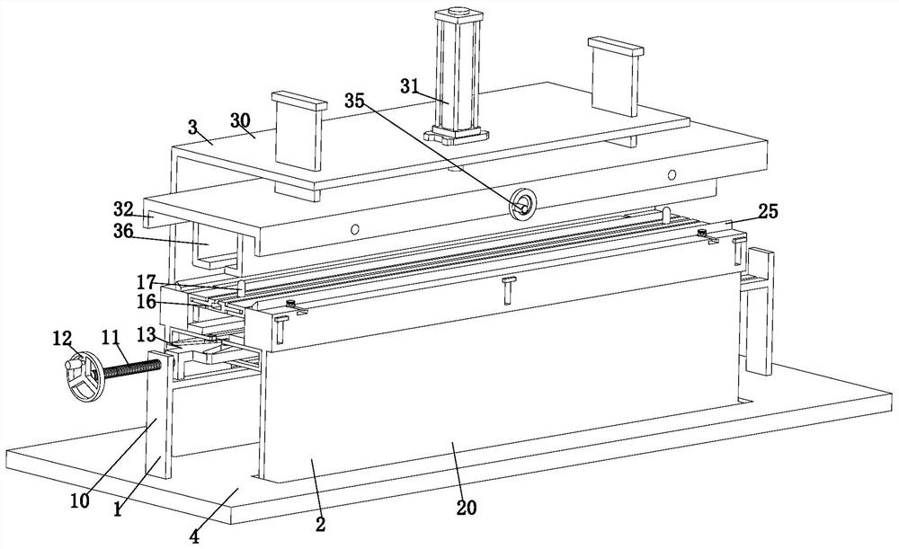
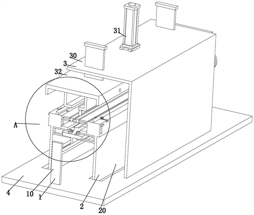
[0038] like Figure 1 to Figure 10 As shown, a trough type cable bridge cover plate stamping forming mold includes a material supporting mechanism 1, a bending mechanism 2, an actuator 3 and a bottom plate 4. The actuator 3 is installed on the bottom plate 4 and is located at the bottom of the actuator 3 There is a bending mechanism 2 directly below, and the bending mechanism 2 is symmetrically installed on the bottom plate 4 through a sliding fit. A supporting mechanism 1 is arranged between the bending mechanisms 2. The material mechanism 1 is connected to the bending mechanism 2 through a movable connection, where...


PUM


Abstract

The invention provides a groove type cable bridge cover plate punch forming die and a punching method thereof. The groove type cable bridge cover plate punch forming die comprises a material supporting mechanism, a bending mechanism, an executing mechanism and a bottom plate. The problems that due to the fact that the two side edges of a cover plate formed and machined at present are bent, internal stress is generated, outward expansion and springback are caused, the material clamping condition can be caused, the cover plate is difficult to take, and the labor intensity of workers is increased are solved; the forming die can only conduct extrusion forming treatment on raw material plates of one type and size, when extrusion forming is conducted on the raw material plates of different widths, lengths or thicknesses, the corresponding forming die needs to be replaced, the production efficiency of a factory is reduced, and the production cost of the cover plate is increased; the raw material plates cannot be accurately positioned in the extrusion forming process, position deviation is caused, size deviation of the formed cable bridge cover plate can be caused, and the actual use requirement cannot be met; and the problems that the surfaces of the raw material plates are prone to being scratched in the extrusion forming process, and the forming quality of the cover plate is reduced are solved.

Description

technical field [0001] The invention relates to the technical field of stamping and forming of cable bridge cover plates, in particular to a punching forming mold and a stamping method for a trough type cable bridge cover plate. Background technique [0002] Trough-type cable tray is a trough-shaped component bent from a whole steel plate. The conceptual difference between it and the pan frame is that the height and width ratio are different. The pan frame is shallow and wide. The trough-type cable tray has a certain depth and closure. . The trough cable tray is a fully enclosed cable tray, which is most suitable for laying computer cables, communication cables, thermocouple cables and other control cables for high-sensitivity systems. Protection is better. [0003] The trough bridge will be equipped with accessories such as cover plates during installation, which can improve the rigidity of the cable bridge. The cover plate is pressed by steel plate with folds on both si...

Claims


Application Information

Patent Timeline
Patent Type & Authority Applications(China)
IPC IPC(8): B21D22/02B21D37/10B21D43/00B21D45/04
CPCB21D22/02B21D37/10B21D43/003B21D45/04
Inventor 徐剑
Owner 广东联标线管桥架有限公司
Why Eureka
Try Eureka