
Three-electrode double-source excitation plasma generating device

A technology of plasma and generating devices, applied in the field of plasma generating devices, can solve problems such as uneven discharge, increased power supply, safety accidents, etc., and achieve the effects of inconvenient use and coordination, convenient cleaning and replacement, and lower requirements

Active Publication Date: 2021-10-26
CHONGQING UNIV
View PDF13 Cites 0 Cited by
  • Summary
  • Abstract
  • Description
  • Claims
  • Application Information

AI Technical Summary

Problems solved by technology

[0003] To sum up, the existing plasma generation device under atmospheric pressure may have defects such as uneven discharge, difficulty in starting the discharge, low energy of the particles generated by the discharge, or serious heat generation due to excessive energy, and the need for an additional cooling structure under a single power supply. When there are two power supplies, due to the design defect of the electrode structure, it is difficult to cooperate with the power supply, and at the same time, it will increase the probability of power supply damage and the probability of safety accidents
Experiments have shown that uniform and stable plasma discharge under atmospheric pressure can effectively enhance the treatment effect, especially when plasma is used for surface modification of materials, it has a great impact on the quality of surface coating. Due to the above defects, existing devices are limited. Wide application of plasma technology under atmospheric pressure

Method used


Image

  • Three-electrode double-source excitation plasma generating device
  • Three-electrode double-source excitation plasma generating device
  • Three-electrode double-source excitation plasma generating device

Examples


Embodiment Construction

[0038] The following will clearly and completely describe the technical solutions in the embodiments of the present invention with reference to the accompanying drawings in the embodiments of the present invention. Obviously, the described embodiments are only some, not all, embodiments of the present invention. Based on the embodiments of the present invention, all other embodiments obtained by persons of ordinary skill in the art without making creative efforts belong to the protection scope of the present invention.

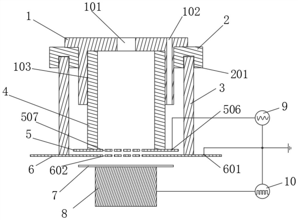
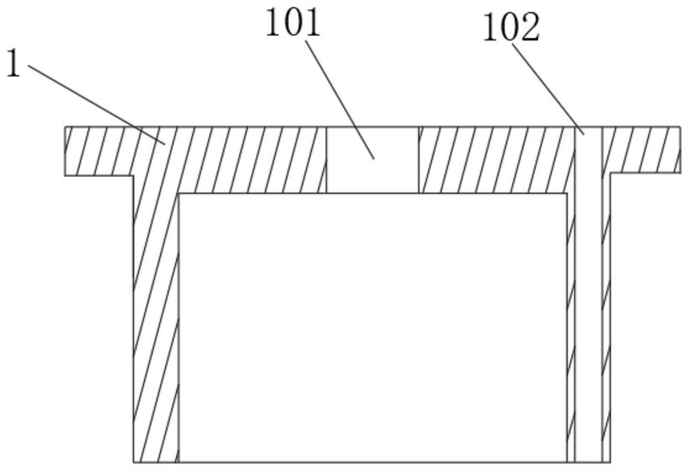
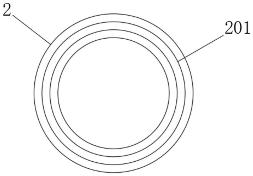
[0039] see Figure 1-12 As shown, a three-electrode dual-source excitation plasma generator includes:

[0040] The inner tube fixing ferrule 1, the outer tube fixing ferrule 2, the outer quartz tube 3 and the inner quartz tube 4, the top of the inner tube fixing ferrule 1 is provided with a cylindrical through hole 102, the outer tube fixing ferrule 2 and the inner tube are fixed The ferrule 1 is threaded and connected, the top of the outer quartz tube 3 is s...


PUM


Abstract

The invention discloses a three-electrode double-source excitation plasma generating device which comprises an inner tube fixing clamping sleeve, an outer tube fixing clamping sleeve, an outer quartz tube and an inner quartz tube, the outer tube fixing clamping sleeve and the inner tube fixing clamping sleeve are connected in a threaded penetrating mode, and the top of the outer quartz tube is connected to the bottom of the outer tube fixing clamping sleeve in a sleeving mode. The top of the inner quartz tube sleeves the bottom of the inner tube fixing clamping sleeve; the high-voltage electrode PCB is arranged at the bottom end of the inner quartz tube; the earth pole PCB is arranged at the bottom end of the outer quartz tube; the high-voltage pole PCB is electrically connected with the first excitation source through a connector by using a wire, and the ground pole PCB is electrically connected with the ground pole through a connector by using a wire; and a dielectric plate is arranged at the top end of the solid electrode. The device has the beneficial effects that three electrodes are used for forming a two-stage discharge structure, so that the loss of raw material gas caused by overhigh gas flow rate is reduced by two-stage discharge while discharge is facilitated, the raw material gas is utilized more sufficiently, and the raw material gas is cracked more sufficiently.

Description

technical field [0001] The invention relates to a biosource excitation plasma generator, in particular to a three-electrode dual-source excitation plasma generator, belonging to the technical field of plasma generators. Background technique [0002] Plasma refers to partially or fully ionized gas, which does not belong to the three common states of matter: solid state, liquid state, and gas state. The favor of the plasma generated under atmospheric pressure is more widely used. In order to make the generated plasma more uniform, a dielectric barrier discharge (DBD) structure is usually used, and the properties of the plasma vary greatly under different power sources, which is reflected in the plasma The state, type, and quantity of active particles are different, so in practical applications, great attention should be paid to the selection of excitation sources. Existing plasma generators mainly include single-power DBD plasma generators, dual-power DBD plasma generators, a...

Claims


Application Information

Patent Timeline
Patent Type & Authority Applications(China)
IPC IPC(8): H05H1/24H05H1/46
CPCH05H1/24H05H1/46
Inventor 熊青黄清华宋一嘉乔俊杰汪传奇杨琦卫丽娟袁博文卢琪
Owner CHONGQING UNIV
Learn More