
Display panel and display device

A display panel and display area technology, applied to static indicators, instruments, etc., can solve the problem of uneven brightness display and achieve the effect of improving uniformity

Active Publication Date: 2022-05-31
WUHAN TIANMA MICRO ELECTRONICS CO LTD
View PDF8 Cites 0 Cited by
  • Summary
  • Abstract
  • Description
  • Claims
  • Application Information

AI Technical Summary

Problems solved by technology

[0004] In the above solution, the brightness of the light-emitting elements in a part of the display area that is multiplexed as the photosensitive element integration area is usually lower than the brightness of the light-emitting elements in other display areas, resulting in uneven brightness display

Method used


Image

  • Display panel and display device
  • Display panel and display device
  • Display panel and display device

Examples


Embodiment Construction

[0022] The features and exemplary embodiments of various aspects of the present invention will be described in detail below, for the purposes of the present invention.

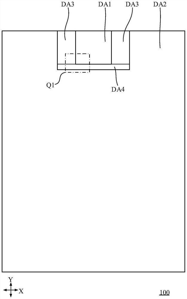
[0025] An embodiment of the present invention provides a display panel, and FIG. 1 is a display panel provided according to an embodiment of the present invention.

[0026] The display panel 100 includes a first display area DA1, a second display area DA2, a third display area DA3 and a fourth display area

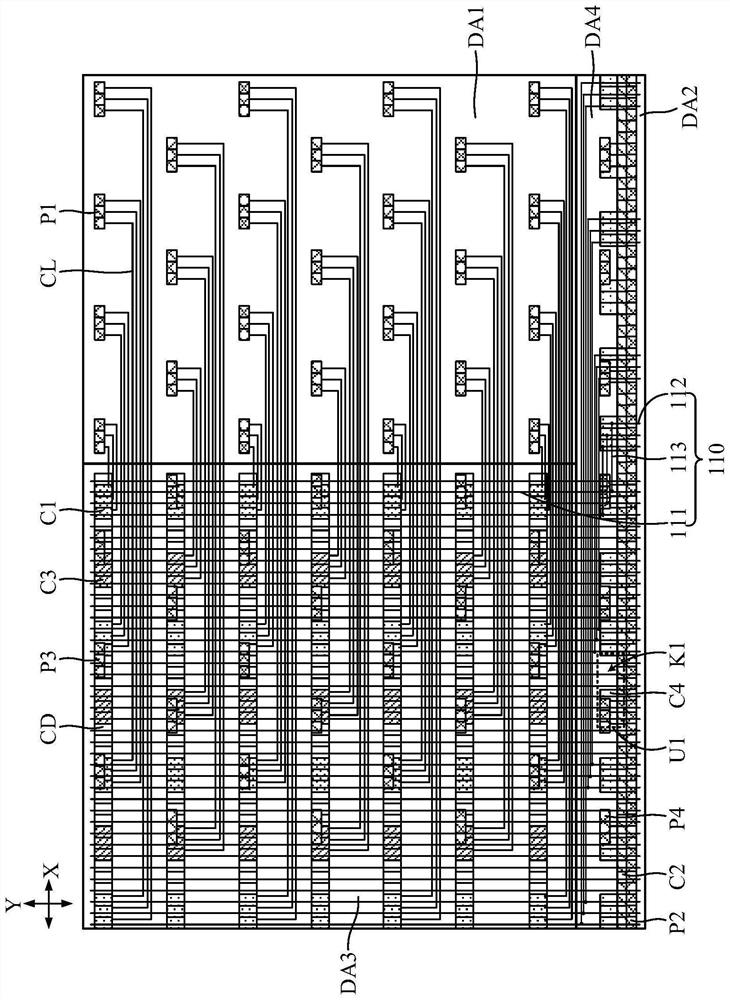
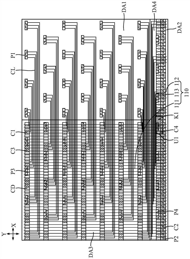
[0027] The display panel 100 also includes a first pixel circuit C1 and a first light-emitting element P1 that are electrically connected to each other and are electrically connected to each other.

[0028] The first light-emitting element P1 is located in the first display area DA1, and the first pixel circuit C1 is located in the third display area DA3. In a

[0029] The fourth pixel circuits C4 are arranged in at least one row in the fourth display area DA4. The fourth pixel circuit C4 in each row includes...


PUM


Abstract

The invention discloses a display panel and a display device. The display panel includes: a first display area, a second display area, a third display area and a fourth display area; a first pixel circuit and a first light emitting element; a second pixel circuit and a second light emitting element; a third pixel circuit and a first light emitting element Three light-emitting elements; a fourth pixel circuit and a fourth light-emitting element, each row of fourth pixel circuits includes at least one first arrangement unit arranged along the first direction, and each first arrangement unit includes N fourth pixel circuits and In the first space, N is a positive integer, wherein, N fourth pixel circuits are adjacently arranged in sequence along the first direction, and the first space is located on one side of the N fourth pixel circuits along the first direction; and a plurality of fourth pixel circuits; A data line, at least one first data line passes through the first space. According to the display panel of the embodiment of the present invention, the uniformity of display brightness of the display panel is improved.

Description

Display panel and display device technical field [0001] The present invention relates to the field of display, in particular to a display panel and a display device. Background technique In electronic devices including display panels, the pursuit of a high screen-to-body ratio with a better visual experience has become a One of the trends in the development of the former display technology. [0003] Taking a mobile phone, a tablet computer, etc. as an example, in the current full-screen solution, at least part of the display area of ​​the display panel is multiplexed. For the photosensitive element integration area. At this time, photosensitive elements such as front cameras and infrared sensing elements can be arranged on the display panel The back of the photosensitive element integration area, the light can pass through the photosensitive element integration area to reach the photosensitive element, realize the front camera, red External induction and other corre...

Claims


Application Information

Patent Timeline
Patent Type & Authority Patents(China)
IPC IPC(8): G09G3/20
CPCG09G3/20G09G2320/0233
Inventor 王美红
Owner WUHAN TIANMA MICRO ELECTRONICS CO LTD
Learn More