Photoresist air isolation system

A photoresist and air technology, applied in coating, device for coating liquid on the surface, coating equipment for photoengraving process, etc., can solve the problem of glue liquid contacting air, etc., and achieve the effect of improving work efficiency

Pending Publication Date: 2021-10-22
宁波润华全芯微电子设备有限公司
View PDF0 Cites 2 Cited by
  • Summary
  • Abstract
  • Description
  • Claims
  • Application Information

AI Technical Summary

Problems solved by technology

[0003] Therefore, the embodiment of the present invention provides a photoresist air isolation system, which can effectively solve the problem of the glue contacting the air when changing the glue bottle or refilling the glue

Method used


Image

  • Photoresist air isolation system
  • Photoresist air isolation system
  • Photoresist air isolation system

Examples


Embodiment Construction

[0032] The following will clearly and completely describe the technical solutions in the embodiments of the present invention with reference to the accompanying drawings in the embodiments of the present invention. Obviously, the described embodiments are only some, not all, embodiments of the present invention. Based on the embodiments of the present invention, all other embodiments obtained by persons of ordinary skill in the art without creative efforts fall within the protection scope of the present invention.

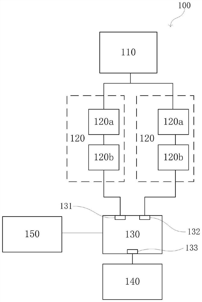
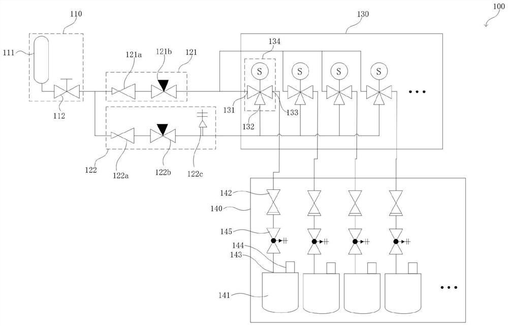
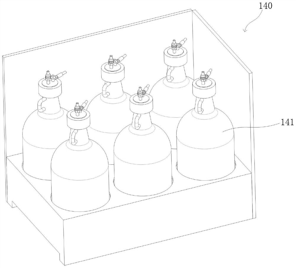
[0033] see Figure 1-2 , which provides a photoresist air isolation system 100 according to an embodiment of the present invention, including: an air supply device 110 , a plurality of pressure regulating devices 120 , a valve island 130 and a photoresist storage device 140 . Wherein, the gas supply device 110 , the pressure regulating device 120 , the valve island 130 and the photoresist storage device 140 are connected in sequence. The gas supply device 110 is u...


PUM


Abstract

The invention discloses a photoresist air isolation system. The system comprises an air supply device; a plurality of pressure regulating devices comprising glue discharging pressure regulating devices and pressure maintaining devices, wherein each pressure regulating device comprises a pressure reducing valve and a throttling valve, the air supply device is sequentially communicated with the pressure reducing valve and the throttling valve, and the pressure reducing valves of the pressure regulating devices are different in working use pressure; a valve terminal provided with a plurality of first air inlets, wherein the first air inlets are communicated with the pressure regulating device; and a photoresist storage device provided with a second air inlet and a photoresist outlet, wherein the second air inlet is communicated with the valve terminal. According to the invention, the problem that the glue solution is in contact with air when the glue bottle is replaced or the glue solution is refilled is effectively solved.

Description

technical field [0001] The invention relates to the field of semiconductor wafers, in particular to a photoresist air isolation system. Background technique [0002] At present, when the photoresist is packaged or the photoresist in the plastic bottle is used, nitrogen pressure supply is often used, or the photoresist is transported by a high-viscosity glue pump. For example, nitrogen gas with a suitable pressure is flushed into the plastic bottle to pressurize the photoresist, so that the photoresist is squeezed out of the plastic bottle. However, in the prior art, there is a device for filling the rubber bottle with nitrogen separately. The problem is that the photoresist in it cannot be fully used up, and there is a residue, and it will be damaged during the process of replacing the rubber bottle or reloading the glue. There is an easy risk of exposure to air, resulting in changes in the properties of the photoresist. Contents of the invention [0003] Therefore, the ...

Claims


Application Information

Patent Timeline
Patent Type & Authority Applications(China)
IPC IPC(8): G03F7/16B05C11/10
CPCG03F7/16B05C11/1013B05C11/1026
Inventor 刘长伟耿克涛陈胜华
Owner 宁波润华全芯微电子设备有限公司
Why Eureka
Try Eureka