
Device and method for testing throttling coefficient of carbon dioxide fracturing fluid

A technology of throttling coefficient and carbon dioxide, which is applied in the preparation of test samples, instruments, analysis materials, etc., can solve the problems of insufficient pressurization of fracturing fluid, complexity, large deviation of throttling coefficient, etc. The effect of test efficiency and accurate measurement value

Inactive Publication Date: 2021-10-22
LULIANG UNIV
View PDF0 Cites 0 Cited by
  • Summary
  • Abstract
  • Description
  • Claims
  • Application Information

AI Technical Summary

Problems solved by technology

But the existing CO 2 The test device for the throttling coefficient of fracturing fluid, the throttling coefficient obtained from the test environment and the actual CO 2- The throttling coefficient deviation in the process of fracturing fluid circulation is large, and it only affects the CO2 through the change of pressure. 2 The throttling coefficient of the fracturing fluid is tested, so that when it is applied to the actual process, the CO 2 After the fracturing fluid enters the rock formation, it causes CO 2 The pressurization of the fracturing fluid is insufficient, and thus the rock formation cannot be fully fractured, and the subsequent pressurization adjustment process is more complicated

Method used


Image

  • Device and method for testing throttling coefficient of carbon dioxide fracturing fluid
  • Device and method for testing throttling coefficient of carbon dioxide fracturing fluid
  • Device and method for testing throttling coefficient of carbon dioxide fracturing fluid

Examples


Embodiment Construction

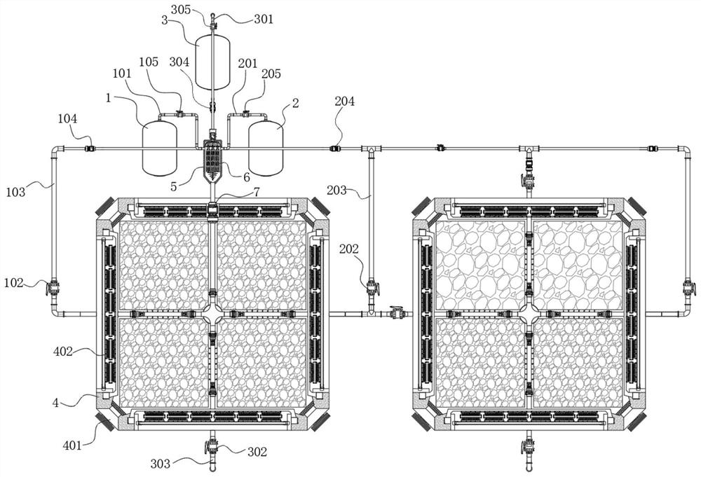
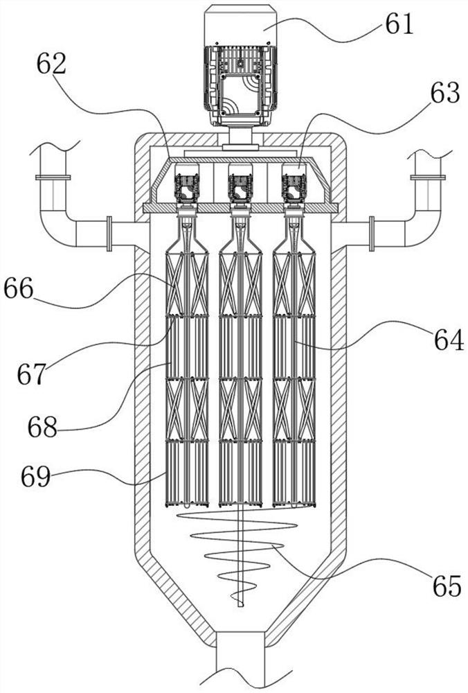
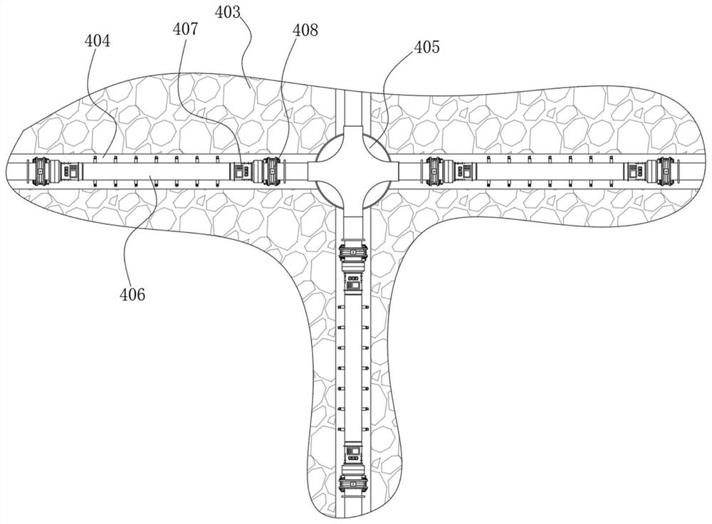
[0038] refer to Figure 1-3 , the present invention provides a technical solution: a test device for the throttling coefficient of carbon dioxide fracturing fluid, which includes a liquid carbon dioxide injection device 1, a fracturing fluid base fluid injection device 2, a proppant injection device 3, and a first simulation test box 4 and a mixed foaming tank 5, the liquid carbon dioxide injection device 1, the fracturing fluid base liquid injection device 2, and the proppant injection device 3 pass through the first introduction pipe 101, the second introduction pipe 201, the third introduction pipe 301 and the The mixing and foaming tanks 5 are connected, and the connected end faces are located at the tank wall near the upper end side of the mixing and foaming tank 5, and a foaming assembly 6 is installed inside the mixing and foaming tank 5;

[0039] The first simulated test box 4 is provided with a simulated well 404, which is in a cross structure, and its internal space ...


PUM


Abstract

The invention discloses a device and method for testing the throttling coefficient of carbon dioxide fracturing fluid, and the device comprises a liquid carbon dioxide injection device, a fracturing fluid base fluid injection device, a proppant injection device, a first simulation test box, and a mixing and foaming tank, the liquid carbon dioxide injection device, the fracturing fluid base fluid injection device and the proppant injection device communicate with the mixing and foaming tank through a first ingress pipe, a second ingress pipe and a third ingress pipe correspondingly, the communicating end faces of the liquid carbon dioxide injection device, the fracturing fluid base fluid injection device and the proppant injection device are all located at the position, close to the upper end side, of the mixing and foaming tank, and a foaming assembly is installed in the mixing and foaming tank, a simulation hoistway is arranged in the first simulation test box and is of a cross structure, the internal space of the first simulation test box is divided into four groups of test chambers, rock stratum samples are arranged in each group of test chambers, and a test device is mounted in the simulation hoistway, the left side end, the right side end and the lower side end of the testing device are communicated with the mixing and foaming tank through a first backflow pipe, a second backflow pipe and a third backflow pipe respectively.

Description

technical field [0001] The invention relates to the technical field of unconventional oil and gas exploitation, in particular to a device and method for testing the throttling coefficient of carbon dioxide fracturing fluid. Background technique [0002] In the field of oil and gas reservoir exploitation, after a certain stage of oil well exploitation, its production capacity and permeability will be reduced. In order to further increase production capacity, fracturing technology will be used. The fracturing methods can be divided into two categories: hydraulic fracturing and high-energy gas fracturing. Among them, using CO 2 The fracturing method can reduce the amount of liquid entering the oil and gas layer. During the fracturing process, it has the characteristics of high viscosity and good sand-carrying performance. 2 Foam fracturing technology has a better fracturing effect; however, due to the large differences in the internal rock structure of different oil and gas l...

Claims


Application Information

Patent Timeline
IPC IPC(8): G01N25/20G01N7/10G01N1/38
CPCG01N25/20G01N7/10G01N1/38
Inventor 辛利伟
Owner LULIANG UNIV
Learn More