
Vertical shaft cage guide flaw detection and deformation distributed optical fiber monitoring system and monitoring method

A technology of distributed optical fiber and monitoring system, which is applied to measurement devices, uses optical devices to transmit sensing components, and converts sensor outputs, etc. The effect of strong anti-interference ability and simple construction

Pending Publication Date: 2021-10-22
扎赉诺尔煤业有限责任公司 +1
View PDF0 Cites 0 Cited by
  • Summary
  • Abstract
  • Description
  • Claims
  • Application Information

AI Technical Summary

Problems solved by technology

Radiation monitoring is to use X-ray flaw detection machine to monitor the cracks of the square steel of the tank road. This method has high monitoring accuracy and large steel penetration thickness. However, when using in the wellbore environment, the stability of the instrument is required to be placed high and the shock absorption is poor.
The geometric distance measurement method uses the basic principle of keeping the steel wire rope to hang the weight vertically downward, establishes the geometric relationship between the position of the tank road and the steel wire rope, and judges the deformation of the tank road. When monitoring the tank road, manual measurement and monitoring accuracy are required. Low
The professional instrument method uses a professional cross-section measuring instrument to monitor the vertical displacement of the tank road to realize independent data collection. However, the monitoring equipment mainly uses inductive and vibrating wire sensors. The sensors are easily disturbed by temperature and electromagnetic radiation in the mine, and have low accuracy. and missing issues

Method used


Image

  • Vertical shaft cage guide flaw detection and deformation distributed optical fiber monitoring system and monitoring method
  • Vertical shaft cage guide flaw detection and deformation distributed optical fiber monitoring system and monitoring method
  • Vertical shaft cage guide flaw detection and deformation distributed optical fiber monitoring system and monitoring method

Examples


Embodiment

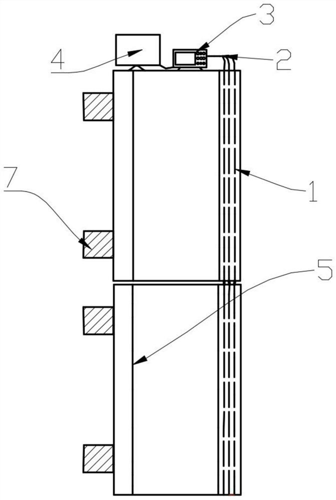
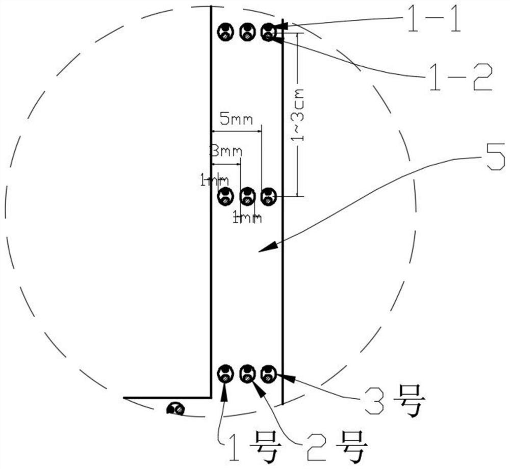
[0040] Embodiment: Using an integrated temperature and strain optical fiber as a sensor, and laying it in the small hole reserved inside the tank road 5, for monitoring the strain value and temperature value of the tank road 5, thereby measuring the temperature of the tank road 5 Flaw detection depth, deflection, strength, bending moment and torsion, etc., to know the condition of tank road 5 in time.

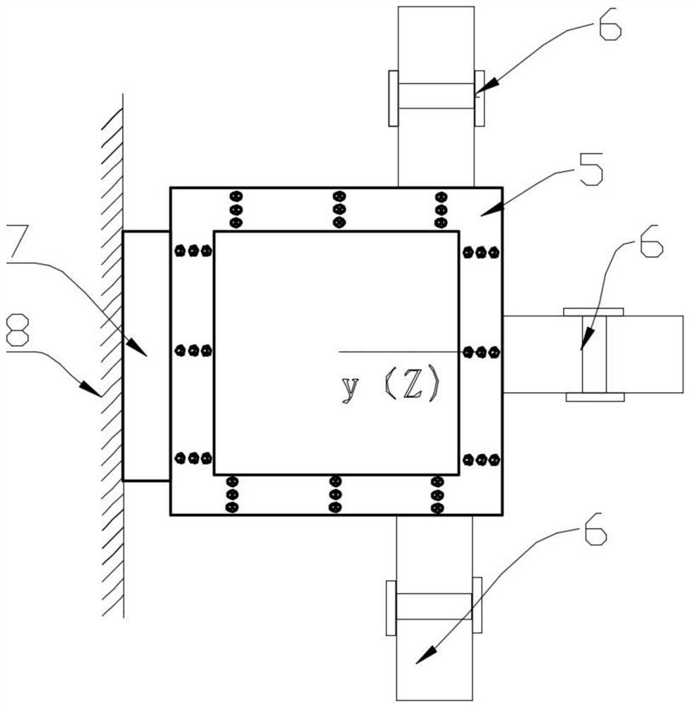
[0041] Such as Figure 1-2 As shown, the vertical shaft tank road 5 is a rectangular parallelepiped structure made by not less than one square steel pipe connected up and down, and its cross section is a square. One side of the tank road 5 is fixed by the tank road beam 7 and the mine wall 8, and the other three The wall is in frictional contact with the rubber wheel 6.

[0042] The installation of the flaw detection and deformation optical fiber distributed monitoring system of shaft tank 5, the specific steps are as follows:

[0043] (1) The tank road 5 is made of square ho...


PUM


Abstract

The invention discloses vertical shaft cage guide flaw detection and deformation distributed optical fiber monitoring system and monitoring method. Sensing optical fiber laying small holes are reserved during manufacturing of the square steel of the cage guide, and sensing optical fibers are packaged into the square steel; through distributed monitoring of strain and temperature within the length range of the cage guide, the relationship between the square steel flaw detection value and strain and temperature is established. Then the abrasion loss and deflection value of the cage guide are determined, the flaw detection depth and deformation of the cage guide are monitored in real time, and early warning information is sent out. The method does not need shaft shutdown monitoring, has the advantages of real-time monitoring, low cost and high precision, and effectively guarantees coal mine safety production and shaft use efficiency.

Description

technical field [0001] The invention relates to a vertical well tank flaw detection monitoring system and method, in particular to a vertical shaft tank flaw detection and deformation distributed optical fiber monitoring system and a monitoring method. Background technique [0002] As an integral part of the mine hoisting system, the tank road plays an important role in the safe mining of coal and the working efficiency of the cage. When the cage in the vertical shaft runs along the tank road, the cage lugs and the tank road rub against each other, which may easily cause the tank road to be worn and thinned due to flaw detection, affecting mine production and causing casualties. [0003] As for the flaw detection and monitoring of the shaft and tank road, ray monitoring, geometric ranging method, professional instrument method and vibration acceleration method are mainly used. Radiation monitoring is to use X-ray flaw detectors to monitor the cracks of square steel in tanks...

Claims


Application Information

Patent Timeline
Patent Type & Authority Applications(China)
IPC IPC(8): G01D21/02G01D5/353
CPCG01D21/02G01D5/35358
Inventor 李寿君朴春德李德军王立艳张洪清崔义焦扬刘晋升赵金来马金海
Owner 扎赉诺尔煤业有限责任公司
Learn More