Fresh air heating and humidifying and exhaust gas impurity removal integrated method

A technology for fresh air and fresh air passages, applied in chemical instruments and methods, separation methods, dry gas layout, etc., can solve the problems of easy blockage of heat exchangers by large particles of impurities, unsuitable heat recovery, and low heat recovery rate. The effect is not good, the temperature rise is reduced, and the heat exchange area is large.

Pending Publication Date: 2021-10-22
GUANGDONG PROVINCE MODERN AGRI EQUIP RES INST
View PDF8 Cites 0 Cited by
  • Summary
  • Abstract
  • Description
  • Claims
  • Application Information

AI Technical Summary

Problems solved by technology

[0004] However, in the existing drying exhaust heat exchange, the main purpose is to use the fresh air for drying materials. Usually, only the temperature of the fresh air is increased without changing the absolute humidity. The temperature of the fresh air is easy to be close to the exhaust temperature. The temperature drop is not much, the heat recovery efficiency is about 30%, and the rest of the heat is discharged to the environment, and the heat recovery rate is low
[0005] Moreover, in the drying work of grains, the drying exhaust contains large-scale impurity particles or straw, while the heat exchange area of ​​the heat pump heat exchanger is large and the fin spacing is small, and large particles of impurities are easy to block the heat exchanger. It can be reused after impurity removal treatment, so the existing heat recovery method is not suitable for the heat recovery of grain drying exhaust, especially for rice drying.

Method used


Image

  • Fresh air heating and humidifying and exhaust gas impurity removal integrated method
  • Fresh air heating and humidifying and exhaust gas impurity removal integrated method
  • Fresh air heating and humidifying and exhaust gas impurity removal integrated method

Examples


Embodiment Construction

[0033] In order for those skilled in the art to better understand the technical solution of the present invention, the present invention will be further described below in conjunction with the examples and accompanying drawings, but the embodiments of the present invention are not limited thereto.

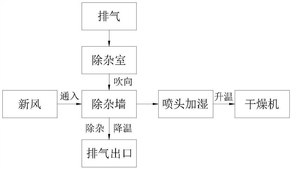
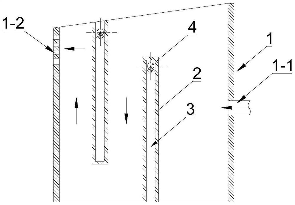
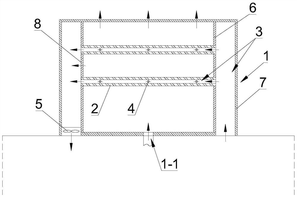
[0034] see Figure 1-3 , the integrated method of fresh air heating, humidification and exhaust impurity removal in this embodiment includes the following steps:

[0035] The exhaust gas is passed into the impurity removal chamber 1, and the exhaust gas is blown from the exhaust inlet 1-1 of the impurity removal chamber 1 to the impurity removal wall 2 provided with a fresh air passage 3 inside.

[0036] The miscellaneous removal wall 2 restricts the flow space and flow direction of the exhaust gas, reduces the flow velocity of the exhaust gas, and the impurities settle down under the action of gravity; at the same time, the exhaust gas is in contact with the miscellaneous removal ...


PUM


Abstract

The invention discloses a fresh air heating and humidifying and exhaust gas impurity removal integrated method. The method comprises the following steps that exhaust gas is introduced into an impurity removal chamber, and the exhaust gas is blown to an impurity removal wall internally provided with a fresh air channel from an exhaust gas inlet of the impurity removal chamber; the impurity removal wall limits the flowing space and the flowing direction of the exhaust gas and reduces the flowing speed of the exhaust gas, and impurities settle down under the action of gravity; meanwhile, the exhaust gas makes contact with the impurity removal wall, and heat is transferred to the impurity removal wall from the exhaust gas and then transferred to the fresh air in the fresh air channel from the impurity removal wall; in the heat exchange process, a spray head of a humidifying mechanism carries out water spraying and humidifying on the fresh air in a fresh air channel, the enthalpy value of the fresh air is increased, and the energy recovery rate is increased; and the exhaust gas after impurity removal is converged into the fresh air through an air return channel and is led to an evaporator of a drying machine together with the fresh air. According to the method, impurity removal can be carried out while the heat is recovered, and method is particularly suitable for rice drying; and in addition, the fresh air is humidified in the heat exchange process, so that the high heat recovery rate is achieved.

Description

technical field [0001] The invention relates to a method for recovering exhaust heat of a dryer, in particular to an integrated method for fresh air heating, humidification and exhaust impurity removal. Background technique [0002] In modern agricultural mechanized production, after grain is harvested, it will be dried by drying equipment for subsequent processing or long-term storage. Among them, most of the existing drying equipment adopts heat pump dryers. Since the efficiency of heat pump dryers is related to the ambient temperature, that is, the heating efficiency and drying effect decrease with the decrease of ambient temperature. When the ambient temperature is lower than 10°C, the heat pump refrigeration system The evaporation temperature of the dryer is generally lower than 0°C, and frost will appear on the evaporator, resulting in a decrease in heat exchange and heating efficiency, and poor drying effect. Therefore, heat pump dryers generally have the problem of p...

Claims


Application Information

Patent Timeline
Patent Type & Authority Applications(China)
IPC IPC(8): F26B25/00F26B21/00B01D45/08F25B47/00
CPCF26B25/005F26B21/002B01D45/08F25B47/00Y02P70/10
Inventor 汤石生叶开愚陈煜龙涂桢楷胡光华曾小辉张金齐易磊黄隆胜龚丽
Owner GUANGDONG PROVINCE MODERN AGRI EQUIP RES INST
Why Eureka
Try Eureka