
Emergency suspension device for seabed sonar robot

A suspension device and robot technology, which is used in motor vehicles, transportation and packaging, special-purpose ships, etc., can solve the problems of equipment detachment, device damage, and the suction cup is prone to misoperation, and achieves the effect of increasing the adsorption effect.

Active Publication Date: 2021-10-22
HARBIN ENG UNIV
View PDF12 Cites 3 Cited by
  • Summary
  • Abstract
  • Description
  • Claims
  • Application Information

AI Technical Summary

Problems solved by technology

Traditional ROV has many problems such as relatively low operating ability, poor mobility, limited number of video transmission channels and transmission distance, poor human-computer interaction ability and scalability, etc., which cannot meet the requirements of ROV in today's marine, military and other related industries or departments. needs
[0003] At present, when the existing submarine sonar robot is in use, because the robot needs to be placed on the seabed, and in order for the robot to float up quickly in case of abnormal conditions, it is necessary to install a floating device outside the robot, but the existing floating device adopts such as The form of automobile anti-collision airbags, such as the existing patented technology CN111252223A and CN105083506A, all utilize the automatic bounce of the airbag in an emergency to realize temporary floating, but the above-mentioned devices all have the following existing technical defects: 1. , expands rapidly and floats upwards. During the floating process of the robot, due to the sudden expansion of the airbag, the buoyancy of the seawater on the airbag is also suddenly applied to the airbag. At this time, the robot is in a state of uniform speed or static, so the state of motion changes suddenly. During the process, the connection between the floating device and the robot will be broken or deformed from time to time, resulting in damage to the device and affecting the rational use of resources; The suction cup type is not easy to disassemble, and it is not convenient to replace the airbag. The suction cup type is prone to misoperation and is easy to be separated from the equipment during the rapid expansion of the airbag; 3. In addition, some existing underwater equipment needs to be kept at Specific attitudes during the floating process, such as tilting attitudes, and the existing tilting attitudes generally need to be adjusted comprehensively by using propellers set in multiple directions on the shell of underwater equipment, and the adjustment efficiency is low

Method used


Image

  • Emergency suspension device for seabed sonar robot
  • Emergency suspension device for seabed sonar robot
  • Emergency suspension device for seabed sonar robot

Examples


Embodiment 1

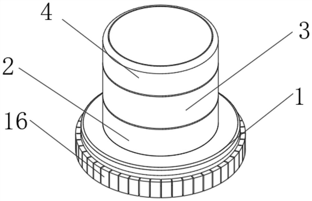
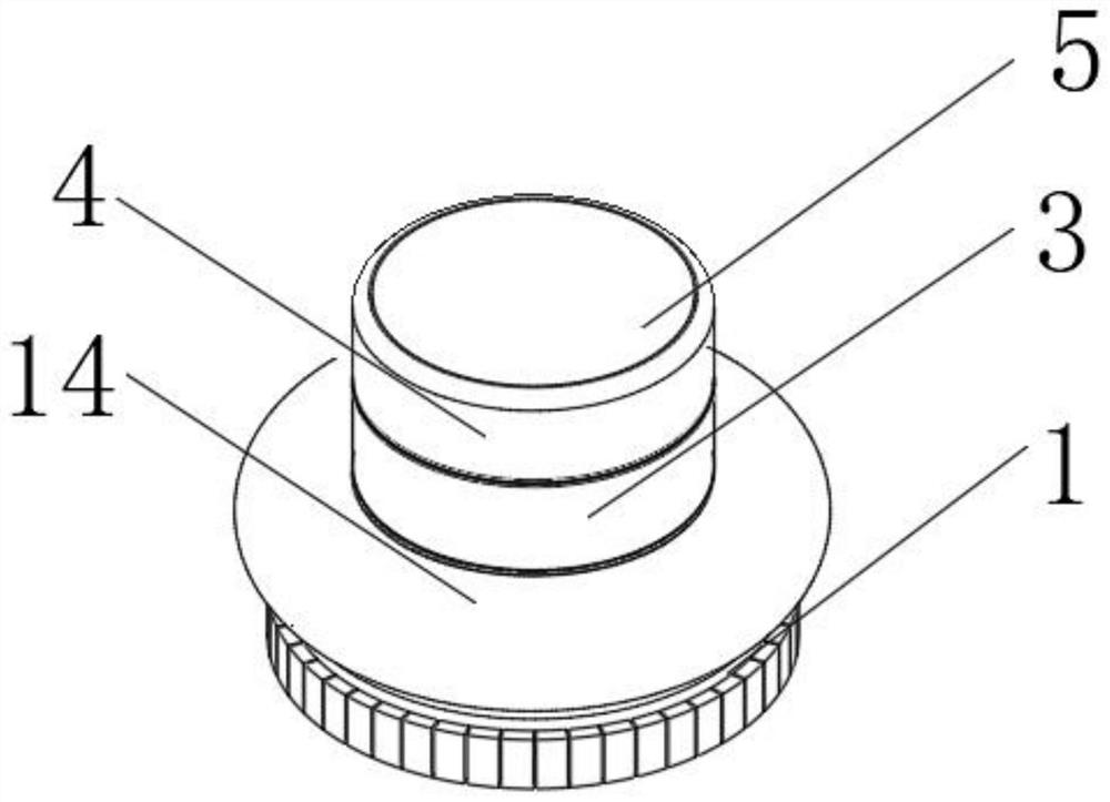
[0027] Embodiment 1, with reference to Figure 1-6 As shown, an emergency suspension device for a submarine sonar robot includes: a connecting base 1, the top of which is sequentially connected with a cylindrical support tube 2, a connecting ring 3 and a top cover 4 from bottom to top, and on the connecting ring 3 The bellows 5 is connected with the top cover 4, and a folded airbag cover 14 is arranged between the connecting ring 3 and the support cylinder 2, and the airbag cover 14 is located in the low-pressure area.

[0028] The slow-rising mechanism includes the No. 1 self-locking motor 6 installed on the inner top surface of the top cover 4 and the mounting seat 8 installed on the inner wall of the connecting ring 3, and the No. 1 screw rod 7 installed on the output shaft of the No. 1 self-locking motor 6 It is threadedly connected with the threaded cylinder 9 installed at the center of the mounting seat 8, and an air bag is arranged between the top cover 4 and the connec...

Embodiment 2

[0051] Embodiment 2, with reference to Figure 1-6 As shown, an emergency suspension device for a submarine sonar robot includes: a connecting base 1, the top of which is sequentially connected with a cylindrical support tube 2, a connecting ring 3 and a top cover 4 from bottom to top, and on the connecting ring 3 The bellows 5 is connected with the top cover 4, and a folded airbag cover 14 is arranged between the connecting ring 3 and the support cylinder 2, and the airbag cover 14 is located in the low-pressure area.

[0052] The slow-rising mechanism includes the No. 1 self-locking motor 6 installed on the inner top surface of the top cover 4 and the mounting seat 8 installed on the inner wall of the connecting ring 3, and the No. 1 screw rod 7 installed on the output shaft of the No. 1 self-locking motor 6 It is threadedly connected with the threaded cylinder 9 installed at the center of the mounting seat 8, and an air bag is arranged between the top cover 4 and the connec...


PUM


Abstract

The invention relates to the technical field of underwater robots, in particular to an emergency suspension device. An emergency suspension device for a seabed sonar robot comprises a connecting base, a slow lifting mechanism and a quick lifting mechanism, whereinthe top of the connecting base is provided with a supporting cylinder, a connecting ring and a top cover, a corrugated pipe is connected between the connecting ring and the top cover, and an air bag sleeve is arranged between the connecting ring and the top cover; the slow lifting mechanism comprises a first self-locking motor and a mounting seat, and a first lead screw is connected with a threaded cylinder at the center of the mounting seat; and the quick lifting mechanism comprises a second self-locking motor and a second lead screw, and the second lead screw is connected with the threaded cylinder at the top of the supporting cylinder. The lead screw is arranged between the top cover and the connecting ring for transmission, the corrugated pipe between the top cover and the connecting ring can be freely adjusted according to needs to form the size, and the robot can slowly move upwards conveniently; besides, a gas generator is arranged in the high-pressure area, an electromagnetic valve is arranged on the partition plate, the expansion degree of the air bag sleeve can be freely adjusted according to needs, and therefore the floating speed of the robot is controlled.

Description

technical field [0001] The invention relates to the technical field of underwater robots, in particular to an emergency suspension device. Background technique [0002] Underwater robot, or remotely controlled unmanned submersible, is a kind of diving equipment that uses its own equipment to carry out human-controlled operations underwater. ROV is currently the most widely used submersible in the world. It is used in marine engineering and military, etc. domain plays an important role. Traditional ROV has many problems such as relatively low operating ability, poor mobility, limited number of video transmission channels and transmission distance, poor human-computer interaction ability and scalability, etc., which cannot meet the requirements of ROV in today's marine, military and other related industries or departments. demand. [0003] At present, when the existing submarine sonar robot is in use, because the robot needs to be placed on the seabed, and in order for the r...

Claims


Application Information

Patent Timeline
Patent Type & Authority Applications(China)
IPC IPC(8): B63G8/24B63C11/52
CPCB63G8/24B63C11/52
Inventor 邓忠超苏军盛明伟朱仲本秦洪德
Owner HARBIN ENG UNIV
Learn More