Test gear dismounting device and use method thereof
A technology for dismantling devices and gears, used in metal processing, metal processing equipment, manufacturing tools, etc., can solve problems such as falling off and test gear leakage, and achieve the effects of convenient installation and operation, wide use, and prevention of top injuries.
- Summary
- Abstract
- Description
- Claims
- Application Information
AI Technical Summary
Problems solved by technology
Method used
Image

Examples
Embodiment 1
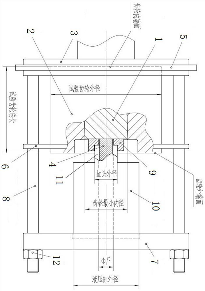
[0051] Such as Figure 1 to Figure 14 As shown, a test gear removal device, the motor test gear 2 is tightly connected with the motor shaft 1, including a chuck 3 for clamping the motor test gear 2, and for rigidly connecting with the end face of the motor shaft 1 The positioning shaft 4 and the power mechanism connected to the positioning shaft 4.
[0052] When using, you can perform the following steps:
[0053] S1, the chuck 3 clamps the motor test gear 2, the positioning shaft 4 is rigidly connected to the end face of the motor shaft 1, and the power mechanism is connected to the positioning shaft 4;
[0054] S2, start the power mechanism, so that the power mechanism drives the motor shaft 1 to move in the direction of falling off from the motor test gear 2 .
[0055] Using the present invention can effectively dismantle the motor test gear 2, avoiding the problem that the motor test gear 2 cannot fall off from the motor shaft 1 due to the leakage problem, and avoiding t...
Embodiment 2
[0071] Such as Figure 1 to Figure 14 As shown, as a further optimization of Embodiment 1, this embodiment includes all the technical features of Embodiment 1. In addition, this embodiment also includes the following technical features:
[0072] A method for using the test gear removal device includes the following steps:
[0073] S1, the chuck 3 clamps the motor test gear 2, the positioning shaft 4 is rigidly connected to the end face of the motor shaft 1, and the power mechanism is connected to the positioning shaft 4;
[0074] S2, start the power mechanism, so that the power mechanism drives the motor shaft 1 to move in the direction of falling off from the motor test gear 2 .
[0075] Using the present invention can effectively dismantle the motor test gear 2, avoiding the problem that the motor test gear 2 cannot fall off from the motor shaft 1 due to the leakage problem, and avoiding the economy caused by heating and cutting the motor test gear 2 and causing the motor t...
Embodiment 3
[0080] Such as Figure 1 to Figure 14 As shown, this embodiment includes all the technical features of Embodiment 1 and Embodiment 2. On the basis of Embodiment 1 and Embodiment 2, this embodiment provides a more detailed implementation mode.
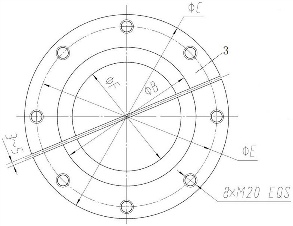
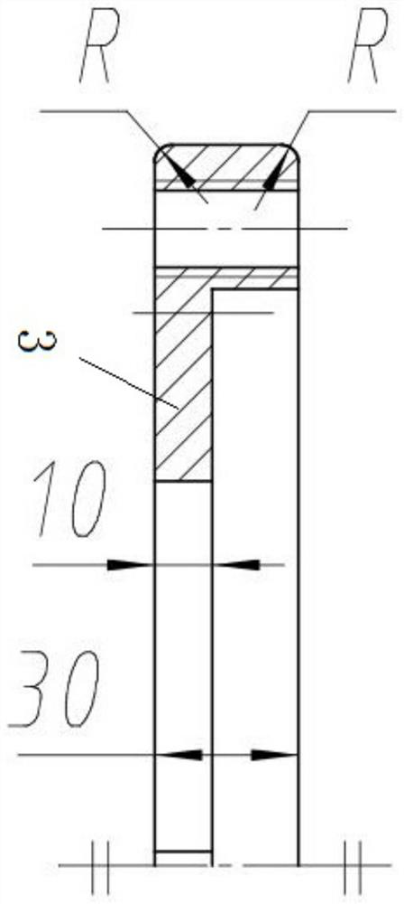
[0081] What the present invention describes is a kind of motor test gear removal device, which is provided with a chuck 3, a hoop 5, a positioning ring 6, a screw 8, a backing plate 9, a top plate 7 and a positioning shaft 4, etc. When in use, the device hoops the motor test gear 2, and applies axial pressure to the hydraulic cylinder 10 by using a 35t or 50t hydraulic cylinder 10 and a hydraulic station / hydraulic pump, so that the motor test gear 2 can be pulled out. The device is compact, convenient and efficient to use, and widely used, and is suitable for removing the motor test gear 2 of the motor.
[0082] Install the backing plate 9 and the positioning shaft 4 on the end face of the motor shaft 1, put the chuck 3 on the inner en...
PUM
 Abstract
Description
Claims
Application Information
 - Generate Ideas
- Intellectual Property
- Life Sciences
- Materials
- Tech Scout
- Unparalleled Data Quality
- Higher Quality Content
- 60% Fewer Hallucinations
Browse by: Latest US Patents, China's latest patents, Technical Efficacy Thesaurus, Application Domain, Technology Topic, Popular Technical Reports.
© 2025 PatSnap. All rights reserved.Legal|Privacy policy|Modern Slavery Act Transparency Statement|Sitemap|About US| Contact US: help@patsnap.com