Slot structure, plastic suction mold frame, plastic suction cutting mold and machining and assembling method thereof

A suction mold and slot technology, which is applied in the fields of suction mold frame, suction die and its processing and assembly, and slot structure, can solve the problems of difficult positioning, difficult to improve efficiency, complicated process, etc., and achieve reasonable structural design. Ingenious, reduce the price of industrial finished products, reduce the effect of processing precision requirements

Pending Publication Date: 2021-10-15
DONGGUAN YISONG CNC TECH
View PDF6 Cites 0 Cited by
  • Summary
  • Abstract
  • Description
  • Claims
  • Application Information

AI Technical Summary

Problems solved by technology

[0005] On the one hand, the existing plastic cutting dies are inconvenient to process, the process is complicated, and due to the hole-to-hole positioning, the precision of the drilling operation is required to be high, making positioning relatively difficult, and the complexity of positioning and the increase in programming costs. Some manufacturers still use manual drilling, which makes it difficult to improve the efficiency, which directly affects the pricing of industrial products; if you want to break the deadlock, making a fuss from the source of production is a better way to break through the status quo of the industry;
[0006] On the other hand, it is inconvenient to install the blister blade in the existing blister knife mold. If there are multiple blade installation positions on one blister knife mold, the adjacent sides of two adjacent blister blades cannot be screwed. Putting in and tightening the column; furthermore, the multi-blade blister knife mold even needs to extend its blades so that they can be fixed from the upper end after bending, which undoubtedly brings complicated processes and high production cost

Method used


Image

  • Slot structure, plastic suction mold frame, plastic suction cutting mold and machining and assembling method thereof
  • Slot structure, plastic suction mold frame, plastic suction cutting mold and machining and assembling method thereof
  • Slot structure, plastic suction mold frame, plastic suction cutting mold and machining and assembling method thereof

Examples


Embodiment Construction

[0051] The following will clearly and completely describe the technical solutions in the embodiments of the present invention with reference to the accompanying drawings in the embodiments of the present invention. Obviously, the described embodiments are only some, not all, embodiments of the present invention. Based on the embodiments of the present invention, all other embodiments obtained by persons of ordinary skill in the art without making creative efforts belong to the protection scope of the present invention.

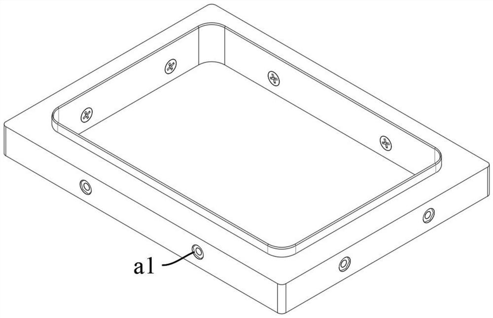
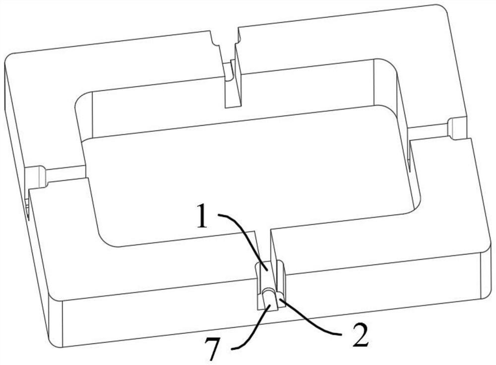
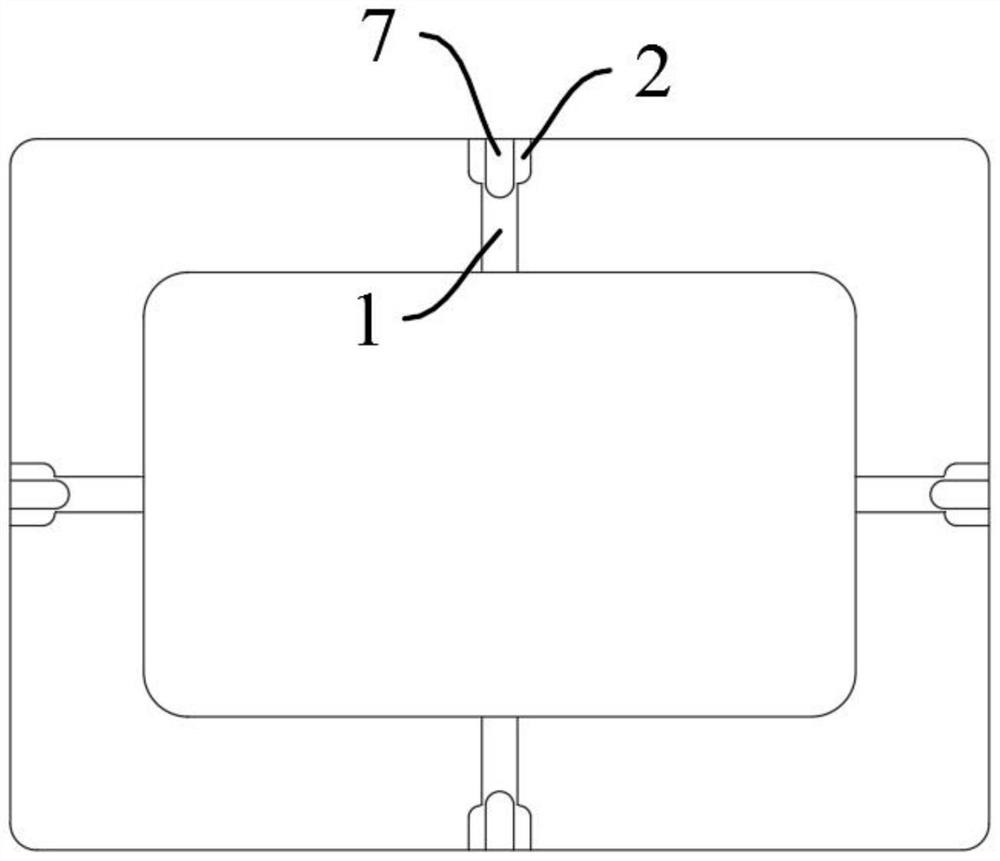
[0052] see Figure 1 to Figure 12 According to another aspect of the present invention, an embodiment of the present invention provides a slot structure according to one aspect of the present invention, including:

[0053] The stud is placed in the positioning groove 1, which can place and locate the stud 4 for pressing and fixing the blister blade 3;

[0054] The nut placement positioning groove 2 communicates with the stud placement positioning groove 1, an...


PUM


Abstract

The invention provides a slot structure, a plastic suction mold frame, a plastic suction cutting mold and a machining and assembling method thereof. The slot structure comprises a stud placing and positioning groove and a nut placing and positioning groove, the stud placing and positioning groove can be used for placing and positioning a stud used for compressing and fixing a plastic suction blade; the nut placing and positioning groove communicates with the stud placing and positioning groove and can be used for placing and positioning a nut for locking the stud; and the stud placing and positioning groove and the nut placing and positioning groove are both grooves, and the groove width of the stud placing and positioning groove is smaller than that of the nut placing and positioning groove. The slot structure is reasonable and ingenious in structural design, the nut is placed and positioned through the nut placing and positioning groove, the stud is placed and positioned through the stud placing and positioning groove, and then the stud is locked through the nut, so that the plastic suction cutting mold is fixed; and the production cost is reduced while the efficiency is improved, the price of industrial finished products is effectively reduced, the competitiveness is improved, and the problems that an existing plastic suction cutting mold is inconvenient to machine, complex in working procedure and inconvenient in the plastic suction blade mounting process are solved.

Description

technical field [0001] The invention relates to the technical field of plastic-absorbing knife molds, in particular to a slot structure, a plastic-absorbing mold frame, a plastic-absorbing knife mold and a processing and assembling method thereof. Background technique [0002] The main principle of the existing plastic processing technology is to heat and soften the flat plastic hard sheet, then vacuum absorb it on the surface of the mold, and then form it after cooling. It is widely used in plastic packaging, lighting, advertising, decoration and other industries. Blister packaging The main advantages are: saving raw and auxiliary materials, light weight, convenient transportation, good sealing performance, in line with the requirements of environmentally friendly green packaging; can pack any special-shaped products, without additional cushioning materials for packing; the packaged products are transparent and visible, beautiful in appearance, It is easy to sell, and is su...

Claims


Application Information

Patent Timeline
Patent Type & Authority Applications(China)
IPC IPC(8): B29C33/38B29C51/32
CPCB29C33/3842B29C51/32
Inventor 池益慧
Owner DONGGUAN YISONG CNC TECH
Why Eureka
Try Eureka