Ophthalmic imaging system

An imaging system and ophthalmic technology, applied in the parts, applications, ophthalmoscopes and other directions of TV systems, can solve production control and manufacturing problems, damage the convenience of system work, limit system diagnostic capabilities, etc., to improve reliability. or the effect of accuracy

Pending Publication Date: 2021-10-12
INTHESMART
View PDF0 Cites 4 Cited by
  • Summary
  • Abstract
  • Description
  • Claims
  • Application Information

AI Technical Summary

Problems solved by technology

[0010] In addition, since there is no way to compensate for the refractive error of the patient's eye, the prior art 11 severely limits the diagnostic capabilities of the system and compromises the convenience of the system's work
In addition, the image beam passing through the imaging channel falls at a large angle to the surface of the

Method used


Image

  • Ophthalmic imaging system
  • Ophthalmic imaging system
  • Ophthalmic imaging system

Examples


Embodiment 1

[0102] 1. Surface data (mm / unit)

[0103]

[0104]

[0105] 2. List of wave aberrations

[0106] Incident field 0 degrees

[0107]

[0108] Tangential fan, incident field 12 degrees

[0109]

[0110]

[0111] Sagittal fan, incident field 12 degrees

[0112]

[0113] Tangential fan, incident field 24 degrees

[0114]

[0115]

[0116] Sagittal fan, incident field 24 degrees

[0117]

[0118] 3. Multi-color diffraction MTF

[0119] Incident field 0 degrees

[0120] spatial frequency tangent sagittal

[0121]

[0122] Incident field 12 degrees

[0123] spatial frequency tangent sagittal

[0124]

[0125] Incident field 24 degrees

[0126] spatial frequency tangent sagittal

[0127]

Embodiment 2

[0129] 1. Surface data (mm / unit)

[0130]

[0131]

[0132] 2. List of wave aberrations

[0133] Incident field 0 degrees

[0134]

[0135] Tangential fan, incident field 12 degrees

[0136]

[0137] Sagittal fan, incident field 24 degrees

[0138]

[0139] Tangential fan, incident field 24 degrees

[0140]

[0141] Sagittal fan, incident field 24 degrees

[0142]

[0143]

[0144] 3. Multi-color diffraction MTF list

[0145] Incident field 0 degrees

[0146] spatial frequency tangent sagittal

[0147]

[0148] Incident field 12 degrees

[0149] spatial frequency tangent sagittal

[0150]

[0151]

[0152] Incident field 24 degrees

[0153] spatial frequency tangent sagittal

[0154]

Embodiment 3

[0156] 1. Surface data (mm / unit)

[0157]

[0158]

[0159] 2. List of wave aberrations

[0160] Incident field 0 degrees

[0161]

[0162]

[0163] Tangential fan, incident field 12 degrees

[0164]

[0165] Sagittal fan, incident field 12 degrees

[0166]

[0167]

[0168] Tangential fan, incident field 24 degrees

[0169]

[0170] Sagittal fan, incident field 24 degrees

[0171]

[0172] 3. Multi-color diffraction MTF list

[0173] Incident field 0 degrees

[0174] spatial frequency tangent sagittal

[0175]

[0176] Incident field 12 degrees

[0177] spatial frequency tangent sagittal

[0178]

[0179] Incident field 24 degrees

[0180] spatial frequency tangent sagittal

[0181]

[0182] As shown in the numerical examples above, the average wave aberration value of the ophthalmic imaging system according to the embodiment of the present invention is about 0.05 to 0.1 and not more than 0.8 at any wavelengt...


PUM


Abstract

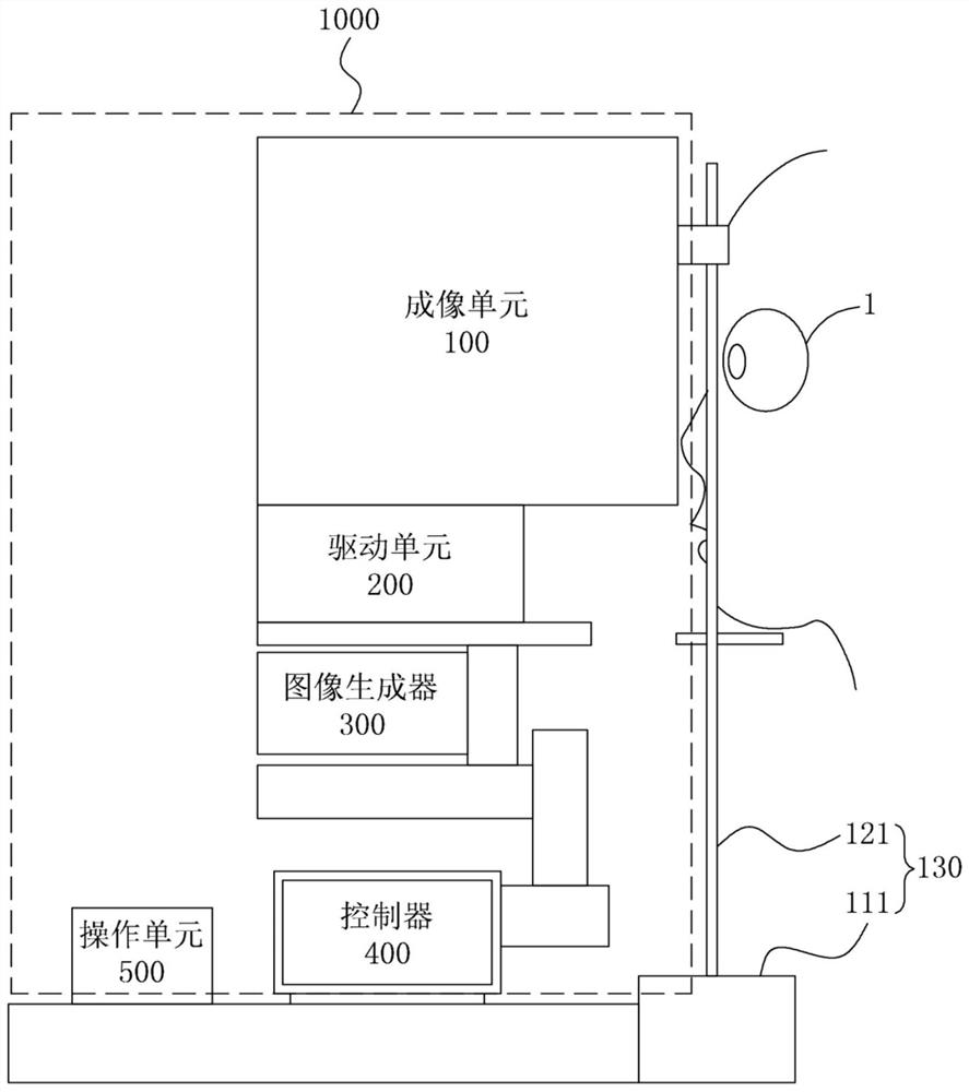
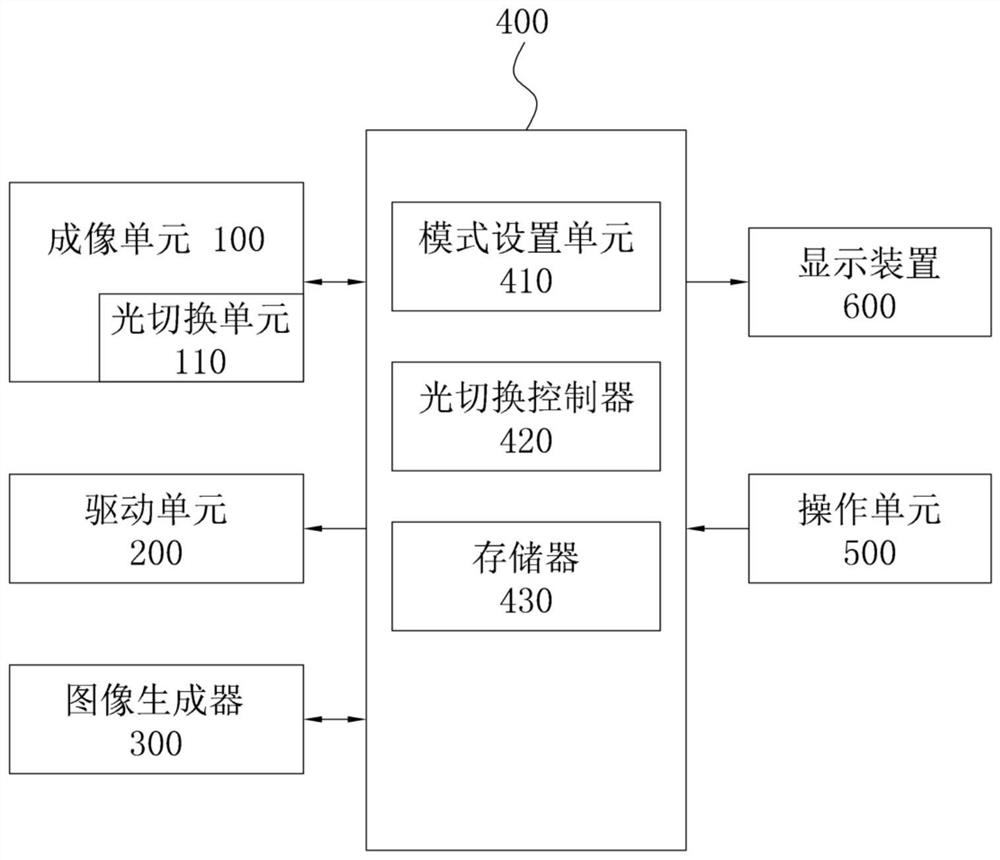
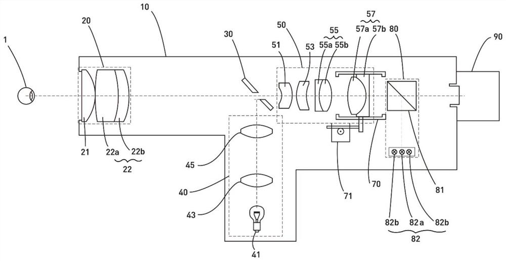
The invention discloses an ophthalmic imaging system and ophthalmic imaging equipment comprising the ophthalmic imaging system. The ophthalmic imaging system comprises an illumination optical system and a photographing optical system. The illumination optical system illuminates the fundus of the subject with light emitted by the light source. The photographing optical system forms an optical path of light reflected from the fundus of the subject. The photographing optical system comprises an ophthalmic lens module, a projection lens module and an aperture stop. The ophthalmic lens module comprises a first positive lens and a first condensing lens which are sequentially arranged from the eye ground of a subject. The projection lens module comprises a negative meniscus lens, a second positive lens, a diverging lens and a second condensing lens, wherein the convex surfaces of the negative meniscus lens, the second positive lens, the diverging lens and the second condensing lens face the opposite direction of the eye ground of the subject. Therefore, according to the ophthalmic imaging system provided by the invention, a subject can watch the aiming light source at different angles, so that the fundus image with a wider fundus area part is shot.

Description

technical field [0001] The invention relates to an ophthalmic imaging system capable of visualizing the fundus and an ophthalmic imaging device comprising the same. Background technique [0002] In general, an optical system for imaging the fundus includes a special ophthalmic lens, a light projection lens, and an aperture stop therebetween. [0003] In particular, the exit pupil position of the ophthalmic lens should be in image space with a predetermined distance (typically a distance less than 3 to 4 times the focal length of the ophthalmic lens) to optically connect said ophthalmic lens, the optical The projection lens is arranged behind the ophthalmic lens, and the optical illumination lens is arranged on the side. [0004] According to prior art 1 (Овчинников Б.В., Черкасова Д.Н.Фундус-камера.RU 2214152 C2.27.06.2003), the fundus camera optical system includes ten components in the imaging channel of visible light, the imaging channel of infrared light The eight comp...

Claims


Application Information

Patent Timeline
IPC IPC(8): G02B13/00G02B13/24G03B15/02A61B3/12A61B3/14
CPCG02B13/00G02B13/24G03B15/02A61B3/12A61B3/14A61B3/0016A61B3/0008A61B3/13A61B3/0083G02B13/0045G02B7/08G02B9/62G02B27/144G02B13/006G02B13/22A61B3/0091G02B15/144113G02B7/02H04N23/55G02B9/06G02B7/04G02B27/14G02B27/0025
Inventor 姜旭李忠熙申一亨伏尔科夫·德米特里·尤里耶维奇帕帕扬·加里·瓦兹根诺维奇
Owner INTHESMART
Why Eureka
Try Eureka