
Energy-saving multi-chamber continuous drying boiling dryer

A boiling dryer, energy-saving technology, used in dryers, drying chambers/containers, drying solid materials, etc., can solve problems such as low drying efficiency, reduce waste, reduce energy, and improve drying efficiency.

Active Publication Date: 2021-10-12
常州市润邦干燥设备科技有限公司
View PDF6 Cites 3 Cited by
  • Summary
  • Abstract
  • Description
  • Claims
  • Application Information

AI Technical Summary

Problems solved by technology

[0005] In order to improve the problem that the boiling dryer can only dry one batch of materials at the same time, resulting in low drying efficiency, this application provides an energy-saving multi-chamber continuous drying boiling dryer

Method used


Image

  • Energy-saving multi-chamber continuous drying boiling dryer
  • Energy-saving multi-chamber continuous drying boiling dryer
  • Energy-saving multi-chamber continuous drying boiling dryer

Examples


Embodiment 1

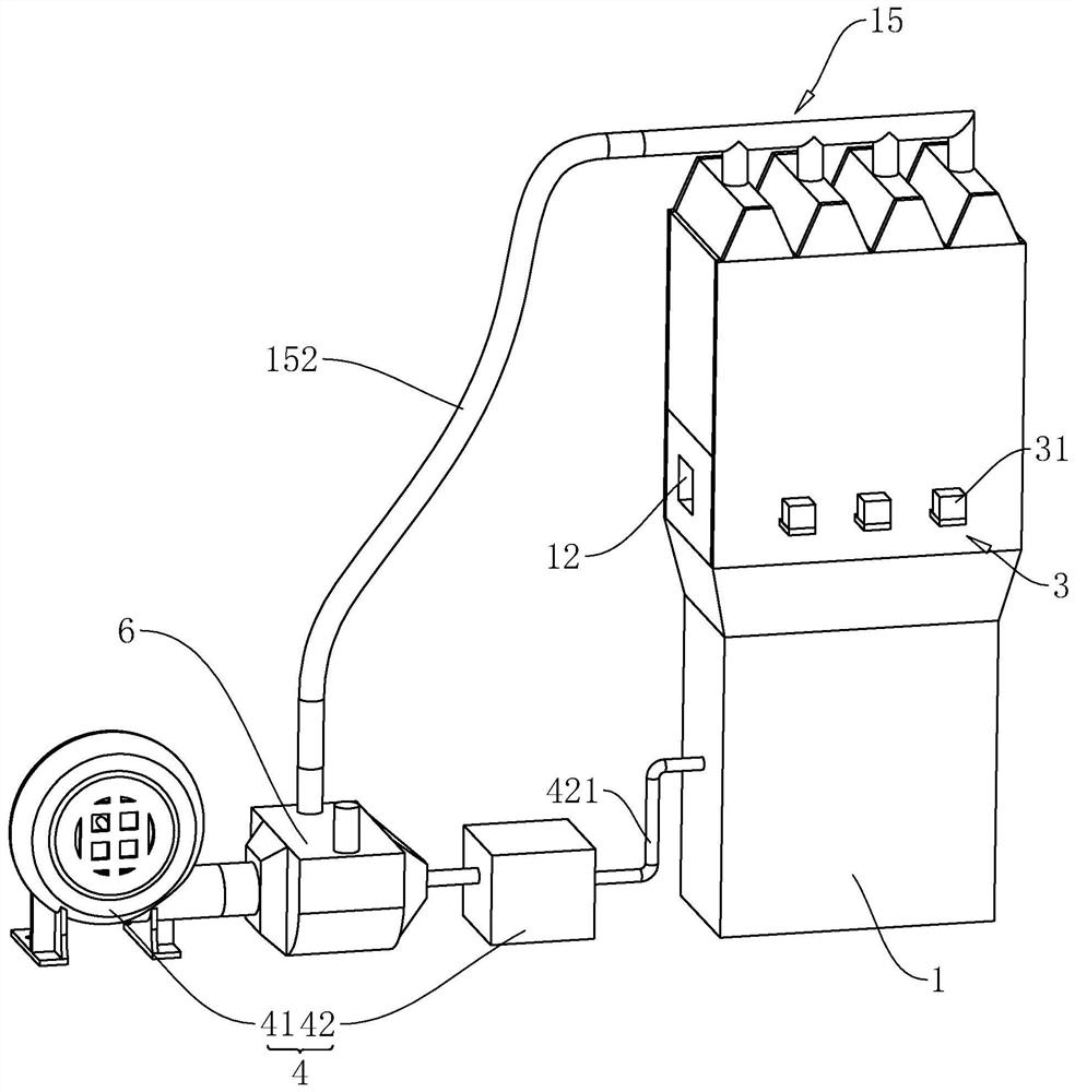
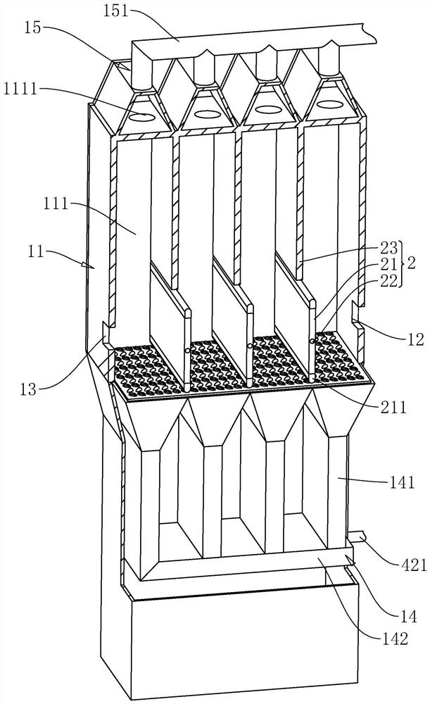
[0040] The application discloses an energy-saving multi-chamber continuous drying fluidized dryer.

[0041] refer to figure 1 and figure 2 , an energy-saving multi-chamber continuous drying fluidized dryer includes a fluidized dryer body 1, a drying chamber 11 is provided in the fluidized dryer body 1, a partition device 2 is provided in the drying chamber 1, and the partition device 2 is arranged along the fluidized dryer body 1. There are multiple arrays in the width direction. The partition device 2 divides the drying chamber 11 into a plurality of drying sub-chambers 111. The fluidized dryer body 1 is connected with a feed port 12 and a discharge port 13. The feed port 12 and the discharge port 13 is oppositely arranged along the width direction of the fluidized dryer body 1, so that after the material enters from the feed port 12, it needs to pass through all the drying sub-chambers 111 before it can be discharged from the discharge port 13. The bottom of the fluidized d...

Embodiment 2

[0048] The application discloses an energy-saving multi-chamber continuous drying fluidized dryer.

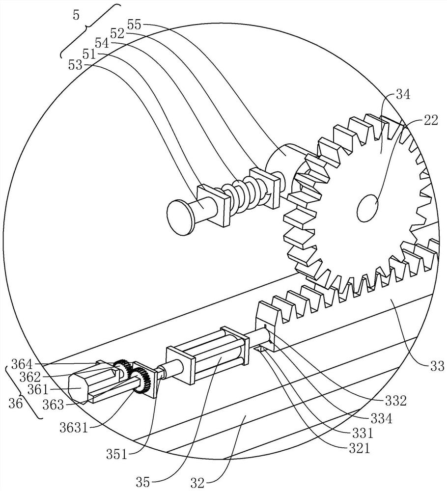
[0049] The difference from Embodiment 1 is that the structure of the driving device 3 has changed.

[0050] refer to image 3 and Figure 4 , the driving device 3 includes a fixed plate 32, a rack 33, a first gear 34 and a telescopic cylinder 35, the fixed plate 32 is fixed on the side wall of the fluidized dryer body 1, and the telescopic cylinder 35 is fixed on the fixed plate 32. One end of the rotating shaft 22 along its axial direction passes through the body 1 of the boiling dryer and is coaxially fixed with the first gear 34. The rack 33 meshes with the first gear 34. The end of the rack 33 facing the fixed plate 32 is fixedly connected with a slider 331 A chute 321 is opened on the fixed plate 32 along the width direction of the fluidized dryer body 1 , and the slider 331 is slidably connected in the chute 321 .

[0051] refer to Figure 4 , the fixed plate 32 is al...


PUM


Abstract

The invention relates to the field of drying equipment, in particular to an energy-saving multi-chamber continuous drying boiling dryer. The dryer comprises a boiling dryer body, a drying cavity used for drying materials is formed in the boiling dryer body, a feeding port and a discharging port are formed in the boiling dryer body, and a partition device is arranged in the drying cavity. The drying cavity is divided into a plurality of drying sub-cavities by the partition device, the feeding port and the discharging port are communicated with the different drying sub-cavities, and a driving device for driving the partition device to be opened and closed is further arranged on the boiling dryer body. The dryer has the effects that continuous drying of the materials is achieved, the drying efficiency is improved, and meanwhile the drying degrees of all batches of the materials output by the boiling dryer body are the same.

Description

technical field [0001] The application relates to the field of drying equipment, in particular to an energy-saving multi-chamber continuous drying boiling dryer. Background technique [0002] Fluidized dryer is a kind of drying equipment, also known as fluidized bed, which is generally composed of heater, fluidized bed host, cyclone separator, bag filter, induced draft fan, and operation table. [0003] The existing authorized announcement number is the relevant patent of CN207317375U, which provides a fluidized dryer, including a box body, a hot air device and an exhaust device connected to the box body, and the box body includes an air-induced dust removal section arranged in sequence from top to bottom, The fluidized bed body and the air inlet section, one end of the fluidized bed body is provided with a feed port, and the end opposite to the feed port is provided with a discharge port, and a porous plate is provided between the bottom of the fluidized bed and the air inl...

Claims


Application Information

Patent Timeline
IPC IPC(8): F26B3/08F26B21/10F26B25/06
CPCF26B3/08F26B21/001F26B21/004F26B21/10F26B25/06Y02P70/10
Inventor 柴文权
Owner 常州市润邦干燥设备科技有限公司
Learn More