Water cooling system simulation device
A simulation device and water-cooling system technology, applied in the direction of measuring devices, instruments, machine/structural component testing, etc., can solve the problems of slow flow of high-temperature gas, limited range of heat absorption coverage, and reduce the accuracy of water-cooling simulation, etc., to achieve The effect of ensuring accuracy, preventing the loss of high-temperature gas, and improving the heat conduction effect
- Summary
- Abstract
- Description
- Claims
- Application Information
AI Technical Summary
Problems solved by technology
Method used
Image

Examples
Embodiment 1
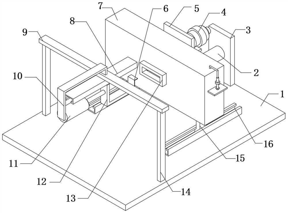
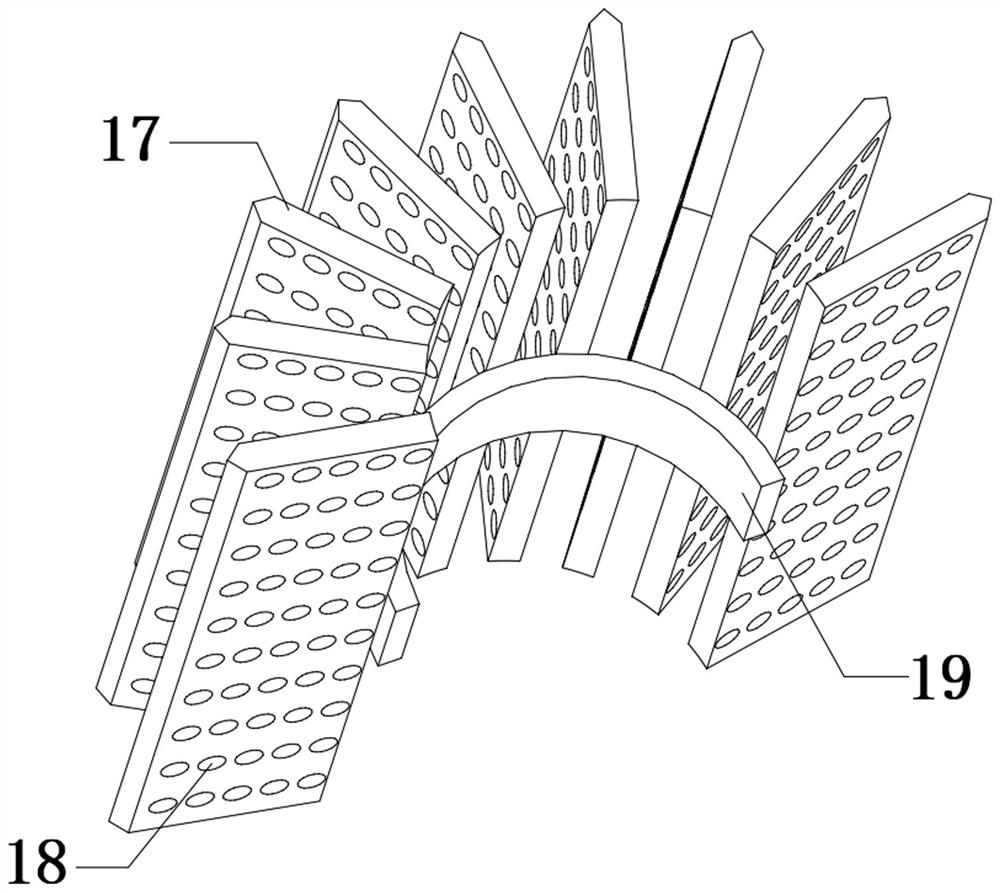
[0027] refer to Figure 1-4 , a water-cooling system simulation device, comprising a bottom plate 1 and a storage frame 7, a through hole is opened on one side of the outer wall of the storage frame 7, and a concentrated heat transfer ring 19 is fixedly connected to the inner wall of the storage frame 7 near the through hole, and the concentrated heat transfer ring The outer wall of 19 is fixedly connected with heat conduction plate 17 equidistantly, and the outer wall of heat conduction plate 17 has heat conduction holes 18 at equal distances, the outer wall of storage frame 7 located outside the through hole is fixedly connected with sealing sleeve 13, and the top outer wall of bottom plate 1 is fixedly connected with Two chutes 16, and the inner walls of the two chutes 16 are slidingly connected with sliders 15, and the two sliders 15 are fixedly connected to the bottom outer wall of the storage frame 7. When performing water cooling simulation, the heat absorber and the cen...
Embodiment 2
[0034] refer to Figure 1-5 , a water-cooling system simulation device, comprising a bottom plate 1 and a storage frame 7, a through hole is opened on one side of the outer wall of the storage frame 7, and a concentrated heat transfer ring 19 is fixedly connected to the inner wall of the storage frame 7 near the through hole, and the concentrated heat transfer ring The outer wall of 19 is fixedly connected with heat conduction plate 17 equidistantly, and the outer wall of heat conduction plate 17 has heat conduction holes 18 at equal distances, the outer wall of storage frame 7 located outside the through hole is fixedly connected with sealing sleeve 13, and the top outer wall of bottom plate 1 is fixedly connected with Two chutes 16, and the inner walls of the two chutes 16 are slidingly connected with sliders 15, and the two sliders 15 are fixedly connected to the bottom outer wall of the storage frame 7. When performing water cooling simulation, the heat absorber and the cen...
Embodiment 3
[0043] refer to Figure 1-5 , a water-cooling system simulation device, comprising a bottom plate 1 and a storage frame 7, a through hole is opened on one side of the outer wall of the storage frame 7, and a concentrated heat transfer ring 19 is fixedly connected to the inner wall of the storage frame 7 near the through hole, and the concentrated heat transfer ring The outer wall of 19 is fixedly connected with heat conduction plate 17 equidistantly, and the outer wall of heat conduction plate 17 has heat conduction holes 18 at equal distances, the outer wall of storage frame 7 located outside the through hole is fixedly connected with sealing sleeve 13, and the top outer wall of bottom plate 1 is fixedly connected with Two chutes 16, and the inner walls of the two chutes 16 are slidingly connected with sliders 15, and the two sliders 15 are fixedly connected to the bottom outer wall of the storage frame 7. When performing water cooling simulation, the heat absorber and the cen...
PUM
 Abstract
Description
Claims
Application Information
 - R&D
- Intellectual Property
- Life Sciences
- Materials
- Tech Scout
- Unparalleled Data Quality
- Higher Quality Content
- 60% Fewer Hallucinations
Browse by: Latest US Patents, China's latest patents, Technical Efficacy Thesaurus, Application Domain, Technology Topic, Popular Technical Reports.
© 2025 PatSnap. All rights reserved.Legal|Privacy policy|Modern Slavery Act Transparency Statement|Sitemap|About US| Contact US: help@patsnap.com