Underground signal receiving and transmitting device

A technology of transmitting device and signal receiving, applied in the field of oil drilling, to achieve the effects of smooth transmission, simple structure and high rotation rate

Active Publication Date: 2021-10-08
SOUTHWEST PETROLEUM UNIV +1
View PDF24 Cites 0 Cited by
  • Summary
  • Abstract
  • Description
  • Claims
  • Application Information

AI Technical Summary

Problems solved by technology

With the development of oil fields, the disadvantages of this technology are becoming more and more obvious

Method used


Image

  • Underground signal receiving and transmitting device
  • Underground signal receiving and transmitting device
  • Underground signal receiving and transmitting device

Examples


Embodiment Construction

[0029] The present invention will be further described below in conjunction with accompanying drawing:

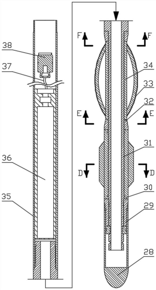
[0030] See attached figure 1 And attached figure 2 , the technical solution of the present invention is: a downhole signal receiving and transmitting device, characterized in that: the downhole signal receiving and transmitting device is located in the outer sleeve, and the two ends of the outer sleeve are connected with the upper drilling tool and the lower drilling tool respectively. Connected through detachable threads; the downhole signal receiving and transmitting device includes a receiving part, a control device, a mechanical assembly and a transmitting mechanism;

[0031]The receiving part includes a connection sleeve 29 connecting the sealing head 28, a centralizer 30 to ensure the vertical operation of the instrument, a receiving antenna 33 for receiving the signal of the lower end instrument, an antenna cover 34 and an antenna cover 32 for restricting the movem...


PUM


Abstract

The invention belongs to the technical field of petroleum drilling, and particularly relates to an underground signal receiving and transmitting device. According to the specific technical scheme, the underground signal receiving and transmitting device comprises a receiving part, a control device, a mechanical assembly and a transmitting mechanism; when the underground signal receiving and transmitting device works, the receiving part receives a signal transmitted by a lower-end instrument, the control device processes the received signal, and a motor is controlled to drive a rotating sleeve, so that a mechanical assembly works; and the mechanical assembly drives a mandrel, so that a rotor continuously and regularly rotates. During rotation, continuous pulses are generated due to the change of the open area of the rotor and a stator, the change of pressure waveforms is monitored on the ground, and measurement data are obtained through decoding and calculation; and according to the underground signal receiving and transmitting device, engineering parameters and geological parameters in the directional drilling process can be obtained in real time, so that a well drilling track and drilling parameters are reasonably adjusted, and measurement and control while drilling in the underground directional drilling process are achieved.

Description

technical field [0001] The invention belongs to the technical field of petroleum drilling, and in particular relates to a downhole signal receiving and transmitting device for extended displacement drilling of directional wells. Background technique [0002] With the deepening of oil and gas resources development, drilling engineering is faced with more complex working conditions, and the difficulty of mining is also increasing. The development of hard-to-produce reserves such as thin oil reservoirs has been carried out on a large scale. In order to increase the exposed area of ​​oil reservoirs in the wellbore and increase the production of oil wells, it is required to drill through the reservoirs with accurate drilling trajectories. Therefore, the requirements for trajectory control accuracy in drilling engineering are increasing, and the precise relative spatial position of the wellbore is more critical. In traditional well logging techniques, when drilling is complete, m...

Claims


Application Information

Patent Timeline
Patent Type & Authority Applications(China)
IPC IPC(8): E21B47/18
CPCE21B47/18H04B1/38H01Q1/04Y02D30/70
Inventor 田家林熊长青唐磊宋豪林毛兰辉杨琳
Owner SOUTHWEST PETROLEUM UNIV
Why Eureka
Try Eureka