Half-through arch bridge suitable for ultra-high-speed railway

An ultra-high-speed, railway technology, used in arch bridges, bridges, bridge construction and other directions, can solve the problems of large beam end corners, difficult to meet traffic requirements, low vertical stiffness, etc., to reduce beam end corners, reduce the calculation span diameter and the effect of reducing the thrust of the arch bridge

Active Publication Date: 2021-10-08
CHINA RAILWAY ERYUAN ENG GRP CO LTD
View PDF5 Cites 0 Cited by
  • Summary
  • Abstract
  • Description
  • Claims
  • Application Information

AI Technical Summary

Problems solved by technology

[0005] The purpose of the present invention is to aim at the mid-supported arch bridge in the prior art, the vertical rigidity is low under the action of the vertical live load of the train, the beam end rotation angle is large, and it is difficult to Satisfies the super high-speed driving requirements with a speed higher than 350km / h, and provides a medium-supported arch bridge suitable for ultra-high-speed railways. The designed structure has good mechanical performance and has sufficient The vertical rigidity reduces the beam end angle generated by the main girder, which can meet the requirements of ultra-high-speed driving and ensure the safety and comfort of high-speed railway driving, especially suitable for flat terrain and poor geological conditions

Method used


Image

  • Half-through arch bridge suitable for ultra-high-speed railway
  • Half-through arch bridge suitable for ultra-high-speed railway
  • Half-through arch bridge suitable for ultra-high-speed railway

Examples


Embodiment

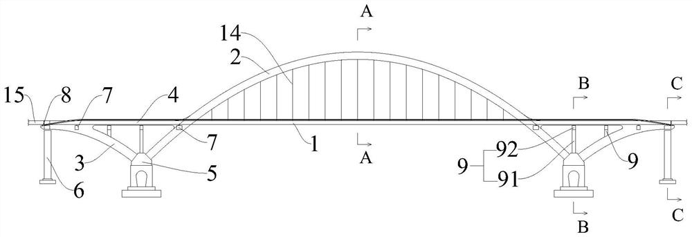
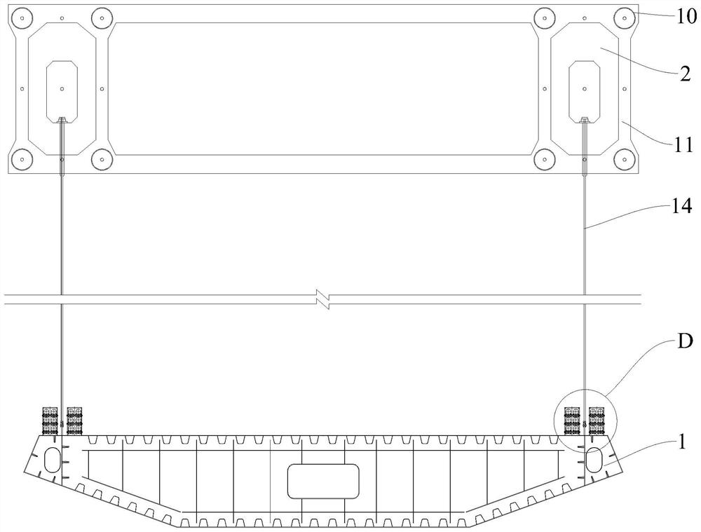
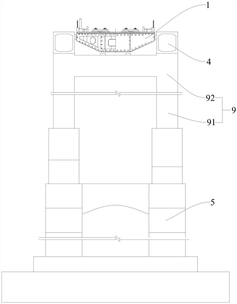
[0053] Such as Figure 1-Figure 2 As shown, a kind of middle-supported arch bridge suitable for ultra-high-speed railways of the present invention includes main girder 1, main arch rib 2, side arch rib 3, rigid tie bar 4, main pier 5 and side pier 6, main girder 1 It is erected between the side piers 6, and the main beam 1 is a continuous structure, the main arch rib 2 is erected between the main piers 5, the side arch rib 3 is erected between the main piers 5 and the side piers 6, and one end of the side arch rib 3 is connected to the The main arch rib 2 is fixedly connected, the other end of the side arch rib 3 supports the main beam 1 , and the rigid tie rod 4 is fixed between the side arch rib 3 and the main arch rib 2 .

[0054] In this embodiment, the main girder 1 adopts a continuous steel box girder structure, and the main girder 1 is erected horizontally between two side piers 6. A main arch rib 2 is arranged on both sides of the main girder 1, and two main arch ribs ...


PUM


Abstract

The invention relates to the technical field of bridge design, and discloses a half-through arch bridge suitable for an ultra-high-speed railway, the half-through arch bridge comprises a main beam, main arch ribs, side arch ribs, rigid tie bars, main piers and side piers, the main beam is erected between the side piers, the main beam is of a continuous structure, the main arch ribs are erected between the main piers, the side arch ribs are erected between the main piers and the side piers, one end of the side arch rib is fixedly connected with the main arch rib, the other end of the side arch rib supports the main beam, and the rigid tie bar is fixed between the side arch rib and the main arch rib. According to the half-through arch bridge suitable for the ultra-high-speed railway, through the cooperation of the side arch ribs and the rigid tie bars and the design of the continuous structure of the main beam, the structural form of the half-through arch bridge has good stress performance and has enough vertical rigidity under the vertical live load effect of a train, the beam end corner generated by the main beam is reduced, the driving requirement of ultrahigh speed can be met, the driving safety and comfort of a high-speed railway are ensured, and the device is particularly suitable for the conditions of flat terrain and poor geology.

Description

technical field [0001] The invention relates to the technical field of bridge design, in particular to a mid-support arch bridge suitable for ultra-high-speed railways. Background technique [0002] The terrain of many rivers is relatively flat, and when the horizontal flow of water flow is too large, piers cannot be set in the river. Cable-stayed bridges are often used as long-span bridges, but the vertical stiffness of cable-stayed bridges is low, which is not suitable for high-speed trains. , so the previous high-speed railway long-span cable-stayed bridges often became the speed limit point. With the further development of high-speed railways, especially the higher and higher requirements for high-speed railways, the speed limit point has gradually become unacceptable for everyone. Therefore, it is necessary to choose an arch bridge with better vertical stiffness as a bridge for high-speed trains. [0003] According to the structural stress, arch bridges can be divided...

Claims


Application Information

Patent Timeline
IPC IPC(8): E01D4/00E01D19/02E01D19/00
CPCE01D4/00E01D19/02E01D19/00
Inventor 向律楷陈思孝陈列彭福兵李锐罗伟元白越谷任奇楚德张澜
Owner CHINA RAILWAY ERYUAN ENG GRP CO LTD
Why Eureka
Try Eureka