Turnover mechanism and turning plate milling machine with same

A technology of flipping mechanism and sliding plate, applied in milling machine equipment, details of milling machine equipment, manufacturing tools, etc., can solve the problems of large load, high safety risk, and large floor space of the flipping mechanism, so as to prevent deformation, improve work efficiency, shorten the The effect of the blanking cycle

Active Publication Date: 2021-10-08
YITELI SHANGHAI SCI TECH CO LTD
View PDF16 Cites 0 Cited by
  • Summary
  • Abstract
  • Description
  • Claims
  • Application Information

AI Technical Summary

Problems solved by technology

Since the size of the worktable may reach 5 meters * 3 meters, if the loading and unloading are designed separately, the floor space will be large
In addition, since the thickness of the workpiece may be only 10mm, the workpiece needs to be turned over together with the workbench. At this time, the load of the turning mechanism will be large, and the safety risk is high
[0004] In the prior art, the turning mechanism of the turning plate milling machine can only turn 90 degrees, and cannot realize automatic unloading

Method used


Image

  • Turnover mechanism and turning plate milling machine with same
  • Turnover mechanism and turning plate milling machine with same
  • Turnover mechanism and turning plate milling machine with same

Examples


Embodiment Construction

[0055] Example embodiments will now be described more fully with reference to the accompanying drawings. Example embodiments may, however, be embodied in many forms and should not be construed as limited to the embodiments set forth herein. Rather, these embodiments are provided so that this disclosure will be thorough and complete, and will fully convey the concept of the example embodiments to those skilled in the art. The same reference numerals denote the same or similar structures in the drawings, and thus their repeated descriptions will be omitted. It should be noted that the orientation or positional relationship indicated by the terms "center", "upper", "lower", "left", "right", "vertical", "horizontal", "inner" and "outer" are Based on the orientation or positional relationship shown in the drawings, it is only for the convenience of describing the present invention and simplifying the description, and does not indicate or imply that the referred device or element m...


PUM


Abstract

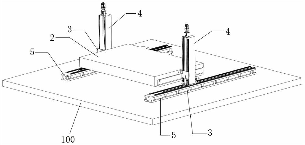
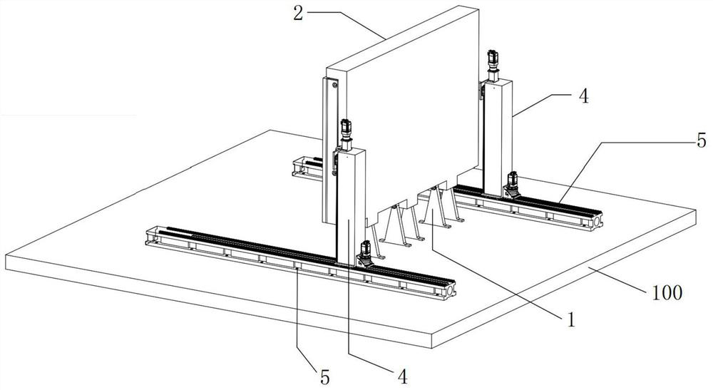
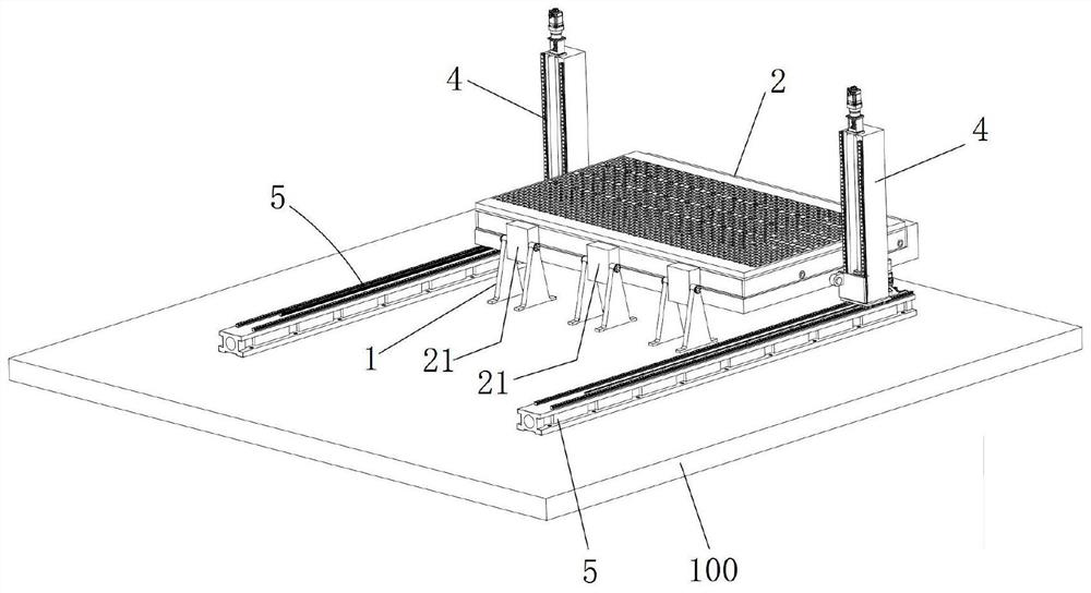
The invention discloses a turnover mechanism. The turnover mechanism comprises a plurality of rotary supports, a workbench, two sliding plates, two first linear driving assemblies and two second linear driving assemblies, wherein the rotary supports are fixed along a rotary center; the workbench comprises a first side face, a second side face and a third side face, and the second side face and the third side face are oppositely arranged and are both perpendicular to the first side face; the first side face is rotationally connected with the rotary supports; the two sliding plates are rotationally connected with the second side face and the third side face of the workbench respectively; the two first linear driving assemblies are vertically and symmetrically arranged on the two sides of the workbench; the two first linear driving assemblies are respectively connected with one sliding plate in a sliding manner so as to drive the two sliding plates to do synchronous linear reciprocating motion within a preset height range; and the two second linear driving assemblies are horizontally and symmetrically arranged on the outer sides of the rotary supports. The invention further discloses a turning plate milling machine with the turnover mechanism. According to the turning plate milling machine, automatic discharging can be achieved, and the working efficiency is greatly improved.

Description

technical field [0001] The invention relates to the technical field of high-end equipment manufacturing, in particular to a plate turning milling machine and a turning mechanism thereof. Background technique [0002] The flip milling machine belongs to the high-end equipment manufacturing equipment urgently needed by domestic aviation and military enterprises. Due to the industry monopoly and technical blockade of foreign advantageous machine tool companies, this type of machine tool is expensive, and the after-sales service is cumbersome and difficult. It is difficult to meet the normal production of related products, and even hinder Delayed the development of my country's national defense industry. [0003] The processing method of the turning plate milling machine is to fix the blank workpiece, erect the surface of the workpiece through the turning mechanism, and move the milling head from the side for milling. The size of the workpiece processed by the flap milling machi...

Claims


Application Information

Patent Timeline
Patent Type & Authority Applications(China)
IPC IPC(8): B23C9/00B23Q7/00
CPCB23C9/00B23Q7/00Y02P70/50
Inventor 刘士孔刘星明肖国正张国
Owner YITELI SHANGHAI SCI TECH CO LTD
Why Eureka
Try Eureka