
Device for bending air conditioner copper pipe of new energy automobile

A new energy vehicle and bending device technology, applied in the field of new energy vehicle processing, can solve the problems of manpower consumption and different bending angles, and achieve the effect of reducing manual operation steps

Pending Publication Date: 2021-10-08
熊武
View PDF6 Cites 0 Cited by
  • Summary
  • Abstract
  • Description
  • Claims
  • Application Information

AI Technical Summary

Problems solved by technology

[0004] In order to overcome the shortcomings of manual bending angles and labor-intensive, the technical problem to be solved: provide a new energy vehicle air-conditioning copper tube bending device that can be bent quickly and is easy to operate

Method used


Image

  • Device for bending air conditioner copper pipe of new energy automobile
  • Device for bending air conditioner copper pipe of new energy automobile
  • Device for bending air conditioner copper pipe of new energy automobile

Examples


Embodiment 1

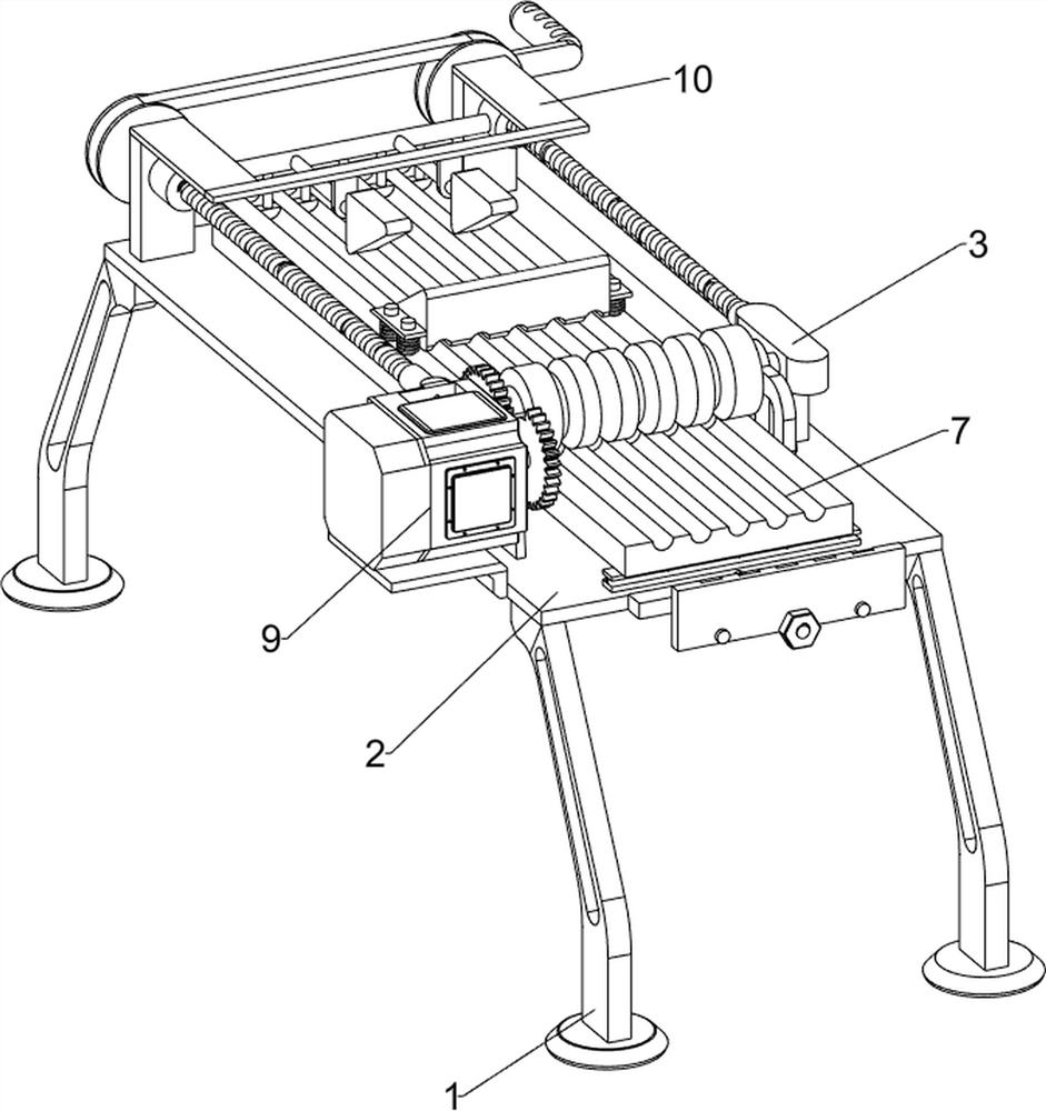
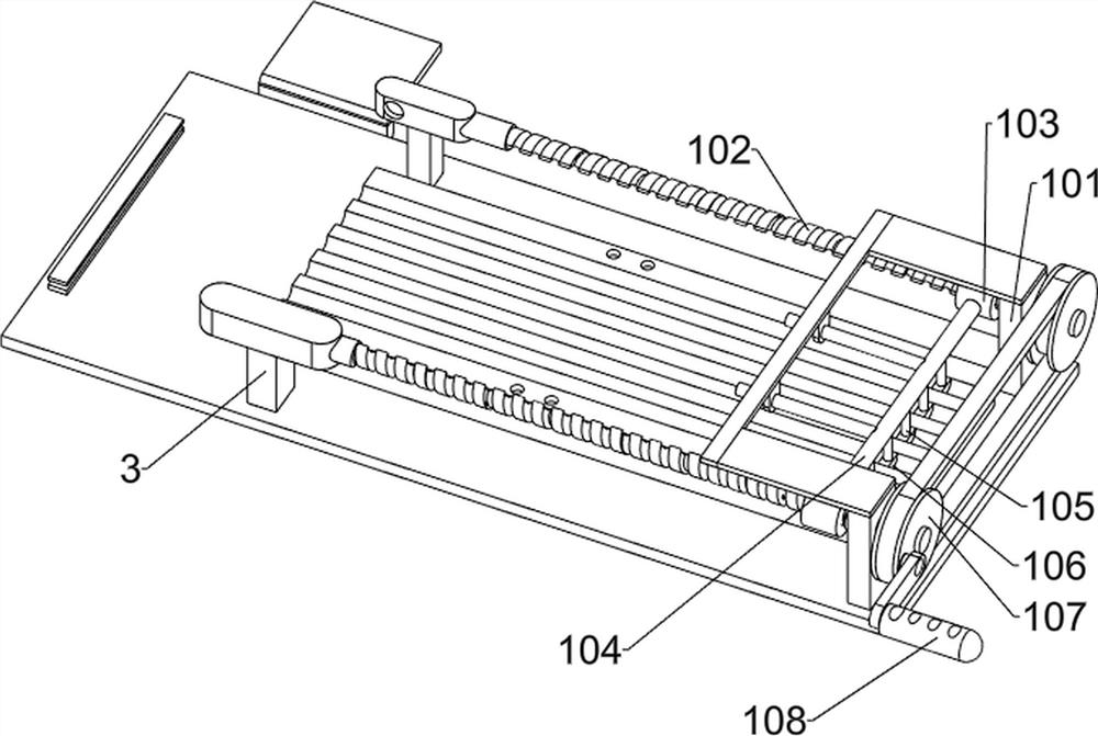
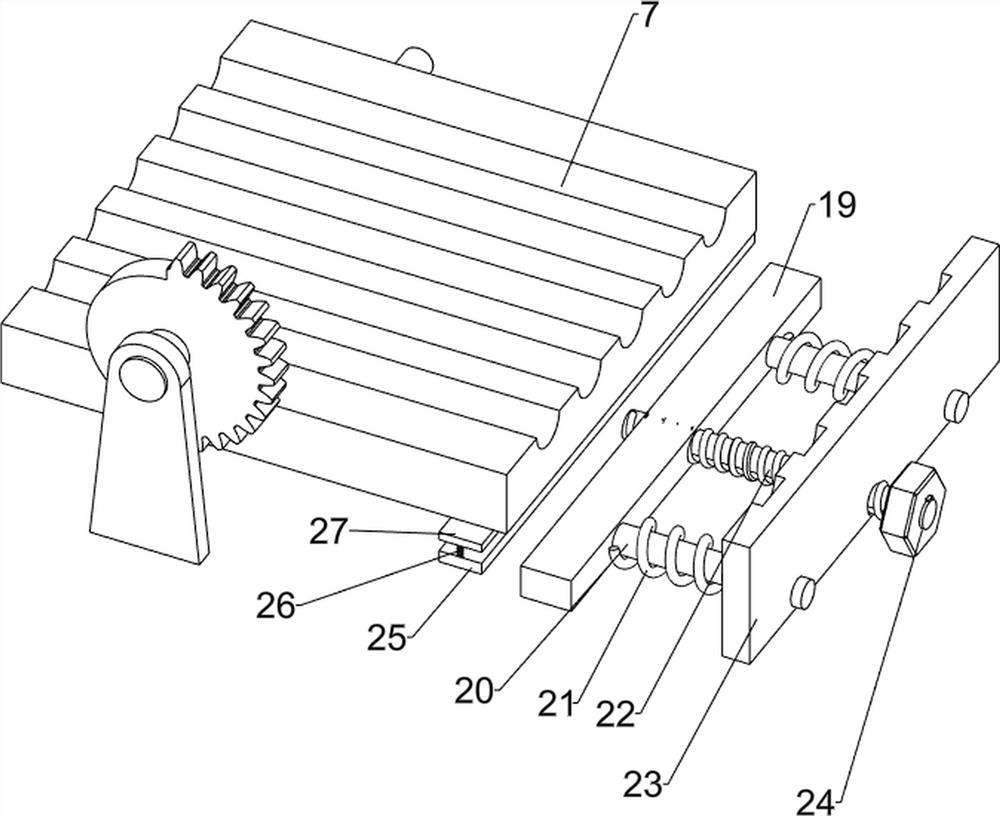
[0024] Such as figure 1 , figure 2 and image 3 As shown, a new energy vehicle air conditioner copper pipe bending device includes a foot 1, a workbench 2, a support seat 3, a transmission shaft 4, a connecting block 5, a connecting shaft 6, a movable plate 7, a placing plate 8, and a driving mechanism 9 And the push mechanism 10, the top of the support foot 1 is provided with a workbench 2, the front side of the top of the workbench 2 is symmetrically provided with a support seat 3, and a transmission shaft 4 is rotatably provided between the two support seats 3, and the left and right ends of the transmission shaft 4 are all provided There are connecting blocks 5, and connecting shafts 6 are arranged on the two connecting blocks 5, and a movable plate 7 is arranged between the two connecting shafts 6, and a semi-arc groove is evenly opened on the movable plate 7, and a Placement plate 8, semi-arc grooves are evenly opened on the placement plate 8, the movable plate 7 coop...

Embodiment 2

[0029] Such as Figure 4 and Figure 5 As shown, on the basis of Embodiment 1, it also includes a guide column 11, a first elastic member 12, a guide plate 13 and a wedge-shaped pressing block 14, and two guides are symmetrically arranged in the middle of the workbench 2 with respect to the central axis of the placement plate 8. A first elastic member 12 is sheathed on the guide column 11 , a guide plate 13 is arranged on the guide column 11 on the same side, and a wedge-shaped pressing block 14 is arranged between the two guide plates 13 .

[0030] During the bending process, the staff can press the wedge-shaped pressing block 14, the first elastic member 12 is compressed, and the wedge-shaped pressing block 14 withstands the upper part of the copper pipe, which can prevent the movement during the bending process. After the bending is completed, the work The personnel releases the wedge-shaped pressing block 14, and the first elastic member 12 drives the wedge-shaped pressin...


PUM


Abstract

The invention belongs to the technical field of new energy automobile machining, and particularly relates to a device for bending an air conditioner copper pipe of a new energy automobile. The device for bending the air conditioner copper pipe of the new energy automobile can realize rapid bending and is simple to operate. The device for bending the air conditioner copper pipe of the new energy automobile comprises supporting legs, supporting seats, a transmission shaft, connecting blocks, connecting shafts and a movable plate, wherein a workbench is arranged at the tops of the supporting legs; the supporting seats are symmetrically arranged at the top of the workbench; the transmission shaft is rotationally arranged between the two supporting seats; the connecting blocks are arranged at the two ends of the transmission shaft; the connecting shafts are arranged on the two connecting blocks; and the movable plate is arranged between the two connecting shafts, and semi-arc grooves are evenly formed in the movable plate. The copper pipe can be adjusted through a pushing mechanism, and then the copper pipe is bent through a driving mechanism.

Description

technical field [0001] The invention belongs to the technical field of new energy automobile processing, and in particular relates to a copper pipe bending device for an air conditioner of a new energy automobile. Background technique [0002] The copper pipe in the air conditioner is the air conditioner refrigerant pipe, and its main function is to store refrigerant and dissipate heat. The air-conditioning refrigerant pipe refers to the pipeline connecting the heat exchanger, valve, compressor and other main refrigeration components through which the refrigerant flows in the air-conditioning system. Usually copper tubes are used. [0003] During the installation process of the copper pipe, the copper pipe needs to be bent. At present, the assembly workers use special fixtures to fix the copper pipe on the periphery, and then bend it around a circular axis. The bending angle is different manually. It is labor-intensive, so it is necessary to design a new energy vehicle air...

Claims


Application Information

Patent Timeline
Patent Type & Authority Applications(China)
IPC IPC(8): B21D7/16B21D7/08
CPCB21D7/16B21D7/08
Inventor 熊武
Owner 熊武
Learn More