
Thermally conductive member and method for manufacturing thermally conductive member

A technology for heat conduction parts and manufacturing methods, which can be used in decoration by conduction heat transfer, digital data processing parts, cooling/ventilation/heating renovation, etc., and can solve problems such as easy deformation, deterioration of working fluid flow, and reduction of heat conduction efficiency.

Inactive Publication Date: 2021-10-01
CHAUN CHOUNG TECH +1
View PDF8 Cites 0 Cited by
  • Summary
  • Abstract
  • Description
  • Claims
  • Application Information

AI Technical Summary

Problems solved by technology

[0005] In the conventional steam room, the pillars are concentrated in the central part of the closed space, so the rigidity of the outer peripheral part of the closed space is low and deformation is easy to occur
The deformation of the closed space deteriorates the flow of the working fluid and may reduce the heat transfer efficiency

Method used


Image

  • Thermally conductive member and method for manufacturing thermally conductive member
  • Thermally conductive member and method for manufacturing thermally conductive member
  • Thermally conductive member and method for manufacturing thermally conductive member

Examples


Embodiment Construction

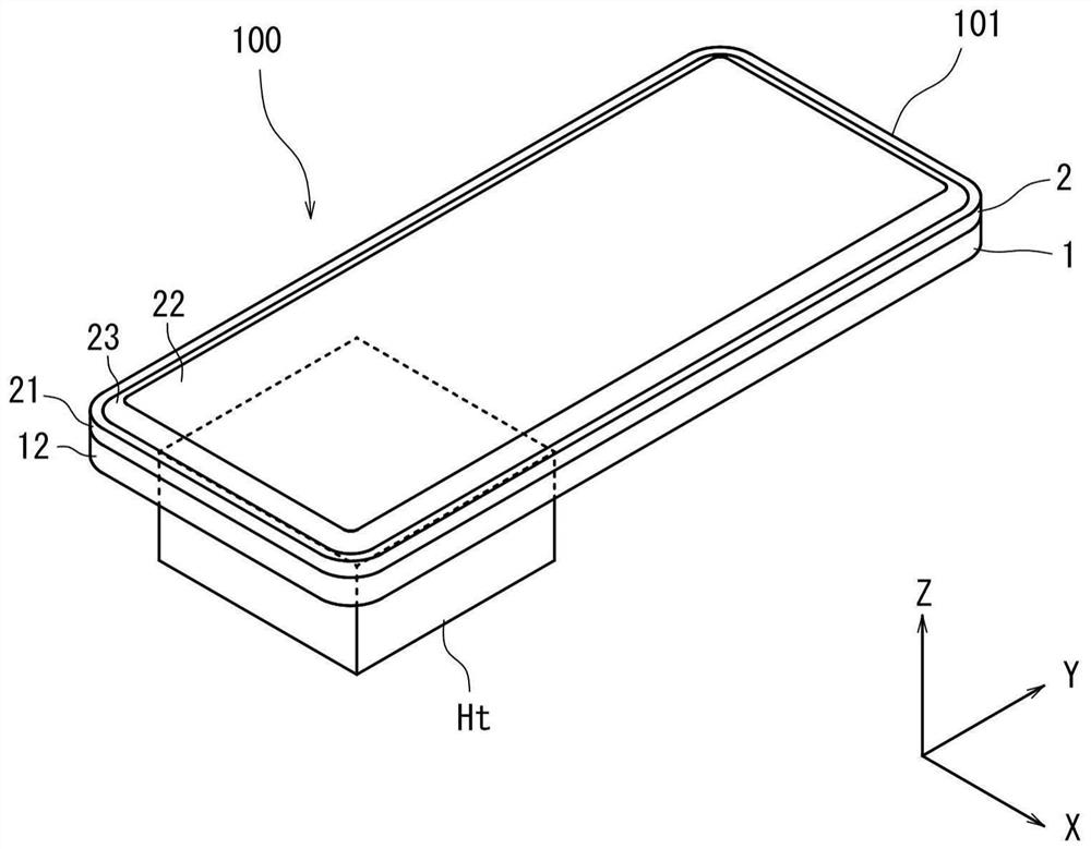
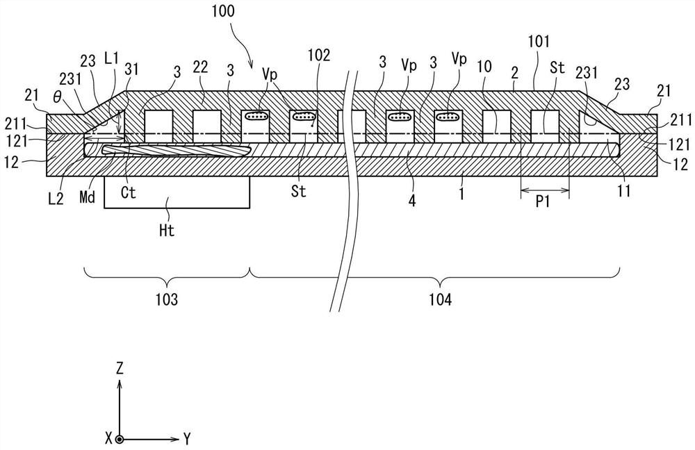
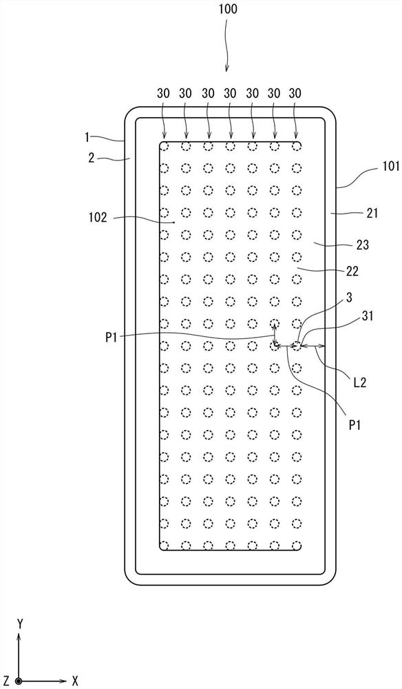
[0021] Hereinafter, exemplary embodiments of the present invention will be described in detail with reference to the drawings. In this specification, the heat conduction member 100 has a rectangular shape in plan view, and the bottom plate portion 1 and the top plate portion 2 overlap each other in the direction of gravity. Let the direction in which the bottom plate part 1 and the top plate part 2 overlap be Z direction. In addition, let the short side direction when viewing the thermally-conductive member 100 from Z direction be X direction, and let a long side direction be Y direction. In addition, the size, shape, and size relationship between structural elements in the drawings are examples, and are not necessarily the same as the actual size, shape, and size relationship between structural elements.

[0022]

[0023] figure 1 It is a perspective view of the heat conduction member 100 of this invention. figure 2 yes figure 1 A cross-sectional view of the thermally ...


PUM


Abstract

A thermally conductive member and a method of manufacturing the thermally conductive member are provided. The thermally conductive member has a housing in which a working medium is sealed. The housing is provided with: a bottom plate part and a top plate part which are overlapped up and down; and a plurality of pillar parts which are in contact with the bottom plate part and the top plate part. The top plate part has a joint portion, a flat plate portion, and an inclined portion connecting an inner end of the joint portion and an outer end of the flat plate portion. The upper end of an inclined inner surface as an inner surface of the inclined portion is in contact with the pillar portion closest to the joint portion. In the joining step, the length from the top plate part to the joining surface of the bottom plate part and the top plate part is set as a first length. The distance from the inner end of a pressing region to a foot that droops from a part of the pillar portion that is closest to the pressing region and that is in contact with the top plate part to the joining surface is a second distance, and the second length is longer than the first length.

Description

technical field [0001] The present invention relates to a thermally conductive component and a method of manufacturing the same. Background technique [0002] Conventionally, in a steam chamber, a plurality of side walls are arranged between an upper plate and a lower plate, and a space enclosed by the upper plate, the lower plate, and the side walls has pillars and cores in contact with the upper plate and the lower plate. In addition, a working fluid is placed in the sealed space of the steam chamber (see, for example, International Publication No. 2017 / 104819). [0003] The vapor chamber has: an evaporating portion heated by an external heat source; and a low-temperature region that condenses the working fluid. In the vapor chamber, the working fluid is heated by the evaporator to evaporate, becomes a gaseous phase, and moves to a low-temperature region. At this time, the working fluid in the gas phase is cooled and condensed. The condensed working fluid returns to the...

Claims


Application Information

Patent Timeline
Patent Type & Authority Applications(China)
IPC IPC(8): H05K7/20G06F1/20
CPCH05K7/20H05K7/2039G06F1/20
Inventor 巽昭生林晃功
Owner CHAUN CHOUNG TECH
Learn More