Distance measuring equipment of laser distance measuring sensor
A technology for measuring distance and laser ranging, which is applied in the direction of measuring devices, radio wave measuring systems, instruments, etc., can solve the problems of cumbersome disassembly and assembly, general use effect, and inability to realize pre-installation and quick connection of laser ranging sensors, and achieve Improve heat dissipation efficiency and enhance the effect of solid performance
- Summary
- Abstract
- Description
- Claims
- Application Information
AI Technical Summary
Problems solved by technology
Method used
Image
Examples
Embodiment 1
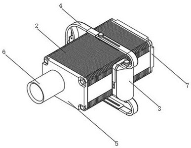
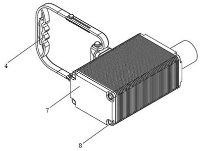
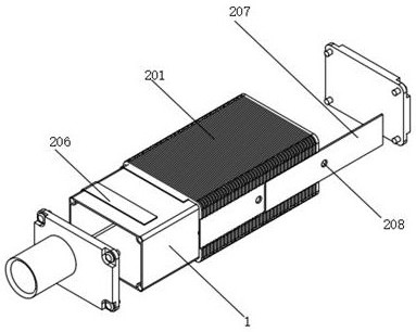
[0030] Such as figure 1 , 2 As shown in , 3, a laser distance measuring sensor measuring distance equipment includes a sensor housing 1, a first cover 5, a round tube 6, a second cover 7 and bolts 8, and one side of the sensor housing 1 is provided with a first cover cover 5, and the other side of the sensor housing 1 is provided with a second cover 7, the first cover 5 and the second cover 7 are connected to the sensor housing 1 by bolts 8, and the end surface of the first cover 5 is provided with A round tube 6, a heat dissipation structure 2 is sleeved on the outside of the sensor housing 1, and a threaded hole is opened in the middle of the front end of the sensor housing 1, and a pre-installed structure 3 is connected to the threaded hole at the front end of the sensor housing 1, and the upper and lower ends of the pre-installed structure 3 A hand-held structure 4 is provided, and a heat dissipation structure 2 is provided outside the sensor housing 1 to realize the heat...
Embodiment 2
[0032] Such as Figure 6 , 7, 8, a pre-installed structure of a laser ranging sensor measuring distance equipment, the pre-installed structure 3 includes a base 303, a first pre-installed slot 304, an embedded block 305, a T-shaped slot 306, a card slot 307, a first Rubber pad 308, slider 309, second pre-installation groove 310, buckle 311, second rubber pad 312, pre-installation block 313, embedded groove 314 and screw rod 315, and the end surface of base 303 is provided with first pre-installation groove 304 , the bottom of the first preloading groove 304 is provided with an embedded block 305, the upper edge of the end surface of the base 303 is provided with a T-shaped groove 306, and the base 303 is provided with a slider 309 at the T-shaped groove 306, and the end surface of the slider 309 is T The type key is inserted into the T-shaped groove 306, a first rubber pad 308 is provided on the lower part of the end surface of the base 303, a second rubber pad 312 is provide...
Embodiment 3
[0034] Such as Figure 5 , 6 , 7, and 8, another pre-installed structure of a laser distance measuring sensor for measuring distance equipment is assembled with a hand-held structure. The pre-installed structure 3 also includes a semicircular block 301 and an adjustment head 302, and the end face of the base 303 is set There is a semicircle block 301, the upper and lower ends of the semicircle block 301 are connected with an adjustment head 302, the adjustment head 302 is screwed with the semicircle block 301, and the semicircle block 301 is fixedly connected with the base 303, the handheld structure 4 includes a connecting rod 401, a jack 402, The first waist hole 403, the first gasket 404, the U-shaped frame 405, the second waist hole 406, the fastening head 407, the handle frame 408, the through groove 409 and the mounting frame 410, and the upper and lower ends of the base 303 are provided with connecting Rod 401, the arc portion of the end of the connecting rod 401 is pr...
PUM
 Abstract
Description
Claims
Application Information
 - R&D Engineer
- R&D Manager
- IP Professional
- Industry Leading Data Capabilities
- Powerful AI technology
- Patent DNA Extraction
Browse by: Latest US Patents, China's latest patents, Technical Efficacy Thesaurus, Application Domain, Technology Topic, Popular Technical Reports.
© 2024 PatSnap. All rights reserved.Legal|Privacy policy|Modern Slavery Act Transparency Statement|Sitemap|About US| Contact US: help@patsnap.com


