Eureka AIR delivers breakthrough ideas for toughest innovation challenges, trusted by R&D personnel around the world.

Cover beam construction auxiliary device and method

An auxiliary device and cover beam technology, applied in bridges, bridge construction, erection/assembly of bridges, etc., can solve problems such as difficult high-altitude construction, hoop slippage accidents, and potential safety hazards

Active Publication Date: 2021-10-01
北京住总集团有限责任公司
View PDF15 Cites 0 Cited by
  • Summary
  • Abstract
  • Description
  • Claims
  • Application Information

AI Technical Summary

Problems solved by technology

In addition, compared with the above-mentioned support method, another commonly used hoop method in the current construction technology of girder cover mainly uses sufficient static friction to bear the load. Although it has obvious advantages in terms of terrain conditions and installation height, However, the application of this method has great limitations. The hoop-type support has requirements on the shape of the pier column; because the value of the friction coefficient between the steel hoop and the pier column in the hoop cantilever beam is difficult to grasp, depending on the flatness of the pier column surface Depending on the degree or roughness of the hoop, the potential safety hazard of hoop slippage accidents during construction is prominent; in addition, in addition to stably assembling the hoop to the pier column, it is still necessary to install multiple longitudinal load-bearing beams and multiple horizontal conduction beams step by step. , multiple supporting trusses, and connecting frames are assembled to the pier columns respectively, which is not only difficult for high-altitude construction, but also has the problem of a huge construction system and cumbersome on-site assembly steps

Method used


Image

  • Cover beam construction auxiliary device and method
  • Cover beam construction auxiliary device and method
  • Cover beam construction auxiliary device and method

Examples


Embodiment Construction

[0040] A detailed description will be given below in conjunction with the accompanying drawings.

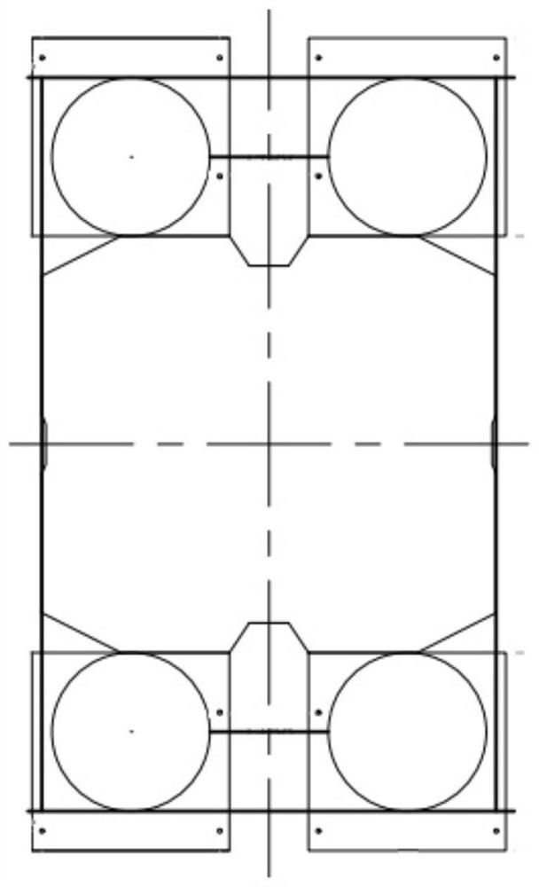
[0041] like figure 1 Shown is a simplified flow chart of the auxiliary method for the construction of the cover beam proposed by the present invention. The auxiliary method for the construction of the cover beam may include pre-construction preparation, installation of the auxiliary support for the cast-in-place cover beam, pouring of the concrete for the cover beam, and demoulding of the concrete for the cover beam. And steps such as dismantling of the cast-in-place cover beam auxiliary support to form a crossbeam located on the top of the pier column 1 and integrated with the pier column 1 .

[0042] like Figure 10 As shown, the cover beam includes a cover beam bottom wall 11 , an extension wall 12 , a side wall 13 , a cover beam top surface 14 and a cover beam inner wall surface 15 . The bottom wall 11 of the cover beam extends along the horizontal direction, and is used fo...


PUM


Abstract

The invention relates to a capping beam construction auxiliary device which at least comprises two triangular support units which are used for being arranged on the two sides of a pier column in the length direction of a to-be-poured capping beam and can be assembled to form an integrated triangular bracket capable of synchronously moving in the length direction of the pier column; a steel supporting frame which surrounds the pier column to form a non-contact space used for containing the pier column, and the two ends of the steel supporting frame are connected to a bottom end frame body of the triangular bracket and a bearing platform located below the pier column correspondingly, so that external force borne by the triangular bracket is transmitted to the bearing platform through the steel supporting frame; and the triangular bracket is hoisted to the steel supporting frame in the mode that a gap is reserved between the triangular bracket and the pier column. The advanced modular solution thought of modern standardization is applied to the technical field of capping beam construction, and the capping beam construction process which is numerous and complicated in original construction system and tedious in on-site assembly steps is simplified to obtain the modular capping beam construction auxiliary system which is high in executability and high in stability.

Description

technical field [0001] The invention relates to the technical field of cover beam construction, in particular to an auxiliary device and method for cover beam construction. Background technique [0002] The cover beam is an important component connecting the upper and lower in the bridge structure. The dead load and live load of the superstructure are transmitted to the pier column and foundation through the cover beam. The cover beam is the connecting component between the bridge box girder and the pier column. The cover beam is the main stress-bearing part of the lower structure of the reinforced concrete simply supported beam bridge located on the top of the pier column. It bears the main supporting role of the bridge. Its construction quality is usually engineering The point of control. There are many construction techniques for the cap beam support, and each technique has its own specific function and technological process, and different construction techniques will pr...

Claims


Application Information

Patent Timeline
IPC IPC(8): E01D21/00
CPCE01D21/00Y02E10/20
Inventor 贾云飞霍艳林周丽苹郭哲苑立彬朱盼黄雪梅杨纬华李斌刘敖然霍俊超钟晨
Owner 北京住总集团有限责任公司
Why Eureka
Eureka Blog
Learn More