Gas-liquid separator for synthesizing anti-aging agent 6PPD
A technology of gas-liquid separator and water separator, which is applied in the direction of amino compound purification/separation, separation method, liquid degassing, etc., and can solve the problem of limited separation effect of gas and liquid phase
- Summary
- Abstract
- Description
- Claims
- Application Information
AI Technical Summary
Problems solved by technology
Method used
Image
Examples
Embodiment 1
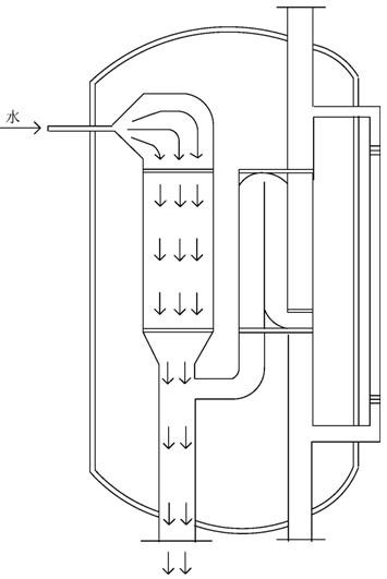
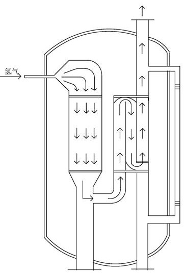
[0030] See attached figure 1 , the cylinder (1) is formed by pressing and welding Q345R steel, which is a vertical container. Both ends of the cylinder (1) are convex, and the overall shell can be covered with aluminum skin. The raw material inlet (2) is fixed in the tangential direction of the cylinder (1) by welding. The distance between the raw material inlet (2) and the top of the cylinder About 20% of the cylinder height. The raw material inlet (2) and the flashing device (3) are fixed by welding, and the flashing device (3) is located inside the cylinder, and can have a certain flashing effect under the condition that the opening angle is not lower than 45°. The flash evaporator (3) passes through a sphericity of π The curved baffle (4) is docked with the vertical ceramic ball post (5), and the interface is fixed by welding. During the installation process, ensure that the ceramic ball column (5) is perpendicular to the ground, and the column is filled in a random pi...
Embodiment 2
[0032] See attached figure 1 , 2, 5, the water in the raw material fluid enters from the raw material inlet (2), after being flashed by the flash evaporator (3), part of the water is converted into water vapor, and then the flow direction is changed into the ceramic ball through the arc-shaped baffle (4) column (5). Because the ceramic ball is hydrophilic, water and water vapor will have adsorption on the ceramic ball, and the flow rate passing through the ceramic ball column (5) will slow down, and finally flow to the water separator (6). The density of water is greater than that of MIBK, and the water is located in the lower layer in the water separator, and the water is discharged through the drain (9). The water distributor (9) should be provided with a certain height, so as to prevent water from entering the branch pipe and bringing it downstream.
Embodiment 3
[0034] See attached figure 1 ,3,5,6, The hydrogen in the raw material fluid enters from the raw material inlet (2), and flows to the ceramic ball column (5) after passing through the flash device (3) and the arc-shaped baffle (4). Ceramic balls have a weak adsorption capacity for hydrogen, and the hydrogen molecules are relatively small, so hydrogen can quickly pass through the ceramic ball column, walk into the branch pipe of the water separator (6) and enter the baffle plate (7). When the hydrogen encounters the barrier of the baffle (7), it can quickly baffle and advance (701) along the plate wall, and can be well separated from MIBK after two stages of baffle, and finally discharged from the gas phase outlet (11).
PUM
| Property | Measurement | Unit |
|---|---|---|
| aspect ratio | aaaaa | aaaaa |
Abstract
Description
Claims
Application Information
 - R&D
- Intellectual Property
- Life Sciences
- Materials
- Tech Scout
- Unparalleled Data Quality
- Higher Quality Content
- 60% Fewer Hallucinations
Browse by: Latest US Patents, China's latest patents, Technical Efficacy Thesaurus, Application Domain, Technology Topic, Popular Technical Reports.
© 2025 PatSnap. All rights reserved.Legal|Privacy policy|Modern Slavery Act Transparency Statement|Sitemap|About US| Contact US: help@patsnap.com


