Fire-fighting water anti-freezing device for fire-fighting

An antifreeze device and fire water technology, which is applied in lighting and heating equipment, heat storage heaters, fluid heaters, etc., can solve the problems of easy freezing of fire water tank water, inability to pump out fire water tank water, and affecting the normal use of fire water tanks, etc. , to achieve the effect of preventing water temperature drop and snow accumulation

Active Publication Date: 2022-03-18
六安华晟智恒工业设计有限公司
View PDF0 Cites 0 Cited by
  • Summary
  • Abstract
  • Description
  • Claims
  • Application Information

AI Technical Summary

Problems solved by technology

[0003] The fire water tank is usually fixedly installed at the highest point of the building. When the temperature is low in winter, the water in the fire water tank will easily freeze, which will easily lead to the failure of the water in the fire water tank to be pumped out in the event of a fire, which affects the fire water tank. normal use

Method used


Image

  • Fire-fighting water anti-freezing device for fire-fighting
  • Fire-fighting water anti-freezing device for fire-fighting
  • Fire-fighting water anti-freezing device for fire-fighting

Examples


Embodiment 1

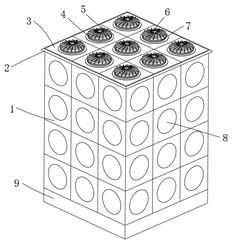
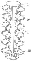
[0029] refer to Figure 1-5 , a fire-fighting water antifreeze device for fire-fighting, comprising a water tank body 1, the bottom outer wall of the water tank body 1 is fixedly connected with a base 9, and the top outer wall of the water tank body 1 is fixedly connected with a top shell 3, and the top inner wall of the top shell 3 There is a wind guide gap between the top outer wall of the water tank body 1, and at least one evenly distributed antifreeze mechanism is arranged inside the water tank body 1. The antifreeze mechanism includes a rotating shaft 10, and the side outer wall of the rotating shaft 10 is fixedly connected with at least three An annular ring 11 evenly distributed in the ring, the annular ring 11 is a wavy annular rod-shaped structure, the top of the rotating shaft 10 extends above the top case 3, the rotating shaft 10 and the top case 3 can slide and rotate relative to each other, and the top of the rotating shaft 10 is fixed An arc-shaped disc 4 is con...

Embodiment 2

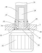
[0036] refer to Image 6 with Figure 7 , a fire-fighting water antifreeze device for fire-fighting. Compared with Embodiment 1, the outer wall of the side surface of the rotating shaft 10 above the top shell 3 is fixedly connected with an upper pressing block 22, and the top shell 3 is located on the top below the upper pressing block 22. The outer wall is fixedly connected with an upper fixing seat 20, the top outer wall of the upper fixing seat 20 is rotatably connected with a fan seat 21, the side outer wall of the fan seat 21 is fixedly connected with a fan blade 24, the top outer wall of the fan seat 21 and the bottom outer wall of the upper pressing block 22 Matching engagement grooves are provided, and the top outer wall of the top shell 3 located below the fan blade 24 is provided with a lower air guide groove 23, and the edge of the bottom outer wall of the arc-shaped disk 4 is rotatably connected with an outer protective shell 6, and the outer protective shell 6 Th...


PUM


Abstract

The invention belongs to the technical field of fire-fighting equipment, in particular to a fire-fighting water antifreeze device for fire-fighting. In view of the problems existing in the prior art, the following solutions are proposed, including a water tank body, the bottom outer wall of the water tank body is fixedly connected with a base, And the top outer wall of the water tank body is fixedly connected with a top shell, an air guide gap is left between the top inner wall of the top shell and the top outer wall of the water tank body, and the interior of the water tank body is provided with at least one evenly distributed antifreeze mechanism, The antifreeze mechanism includes a rotating shaft, and the side outer wall of the rotating shaft is fixedly connected with at least three annular evenly distributed annular rings, the annular rings are wave-ring rod-shaped structures, and the top of the rotating shaft extends to the top of the top shell. The invention can keep the water inside the water tank in a flowing state, and has the effect of anti-freezing. The temperature of the water is heated through heat transfer, so as to achieve the effect of preventing the water temperature from decreasing. .

Description

technical field [0001] The invention relates to the technical field of fire-fighting equipment, in particular to a fire-fighting water antifreeze device for fire-fighting. Background technique [0002] The fire water tank is a kind of fire-fighting facility, which refers to the fire-fighting facilities that provide water sources for the fire brigade during fire-fighting and rescue activities. On the one hand, it fills the fire-fighting water supply pipeline with water, saving the time for filling the pipeline after the fire-fighting water pump is turned on, and winning time for extinguishing the fire. . On the other hand, the pressurization, pressure stabilization system and water tank installed on the roof can ensure that the water column of the fire water gun is full, which plays a decisive role in the success or failure of extinguishing the initial fire. [0003] The fire water tank is usually fixedly installed at the highest point of the building. When the temperature i...

Claims


Application Information

Patent Timeline
Patent Type & Authority Patents(China)
IPC IPC(8): A62C31/00A62C31/28F24H7/02
CPCA62C31/00A62C31/28F24H7/0216
Inventor 徐光磊
Owner 六安华晟智恒工业设计有限公司
Why Eureka
Try Eureka