
Current monitoring device

A current monitoring and current technology, applied in the direction of measuring devices, measuring current/voltage, short-circuit testing, etc., can solve the problems that the current acquisition module cannot achieve accurate measurement, failure identification and reporting, and difficulties in technical upgrading and transformation of the station area. To achieve the effects of rich local alarm indications, convenient networking connection, and obvious local alarm indications

Inactive Publication Date: 2021-09-28
TIANJIN SVRUI INTELLIGENT ELECTRICAL CO LTD
View PDF2 Cites 0 Cited by
  • Summary
  • Abstract
  • Description
  • Claims
  • Application Information

AI Technical Summary

Problems solved by technology

[0004] Based on the existing technology, monitoring devices that can achieve accurate measurement are often unable to detect fault current due to the limitation of the measurement range of the current acquisition module, and cannot realize fault identification and reporting; monitoring devices that can detect fault current often cannot achieve accurate measurement by the current acquisition module , topology identification and line loss analysis based on accurate electric energy measurement cannot be realized; the monitoring device that needs to realize accurate electric energy measurement and wide current range fault detection at the same time, due to the limitations of existing technology, requires two sets of current acquisition modules and two signal processing systems, This solution leads to large size, high cost, complex technology and long development cycle of the monitor, which brings difficulties to the technical upgrading and transformation of the existing station area

Method used


Image

  • Current monitoring device
  • Current monitoring device
  • Current monitoring device

Examples


Embodiment Construction

[0031] Features and exemplary embodiments of various aspects of the invention will be described in detail below. In the following detailed description, numerous specific details are set forth in order to provide a thorough understanding of the present invention. It will be apparent, however, to one skilled in the art that the present invention may be practiced without some of these specific details. The following description of the embodiments is only to provide a better understanding of the present invention by showing examples of the present invention. The present invention is by no means limited to any specific configuration and algorithm presented below, but covers any modification, substitution and improvement of elements, components without departing from the spirit of the present invention.

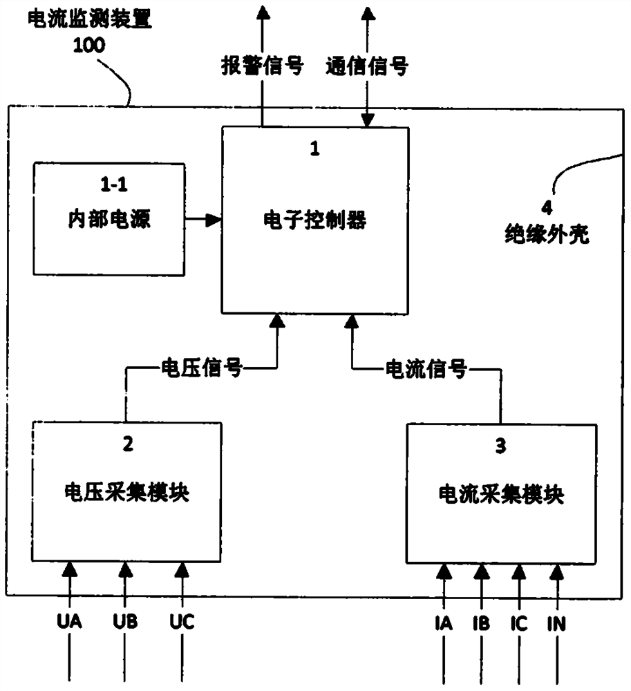
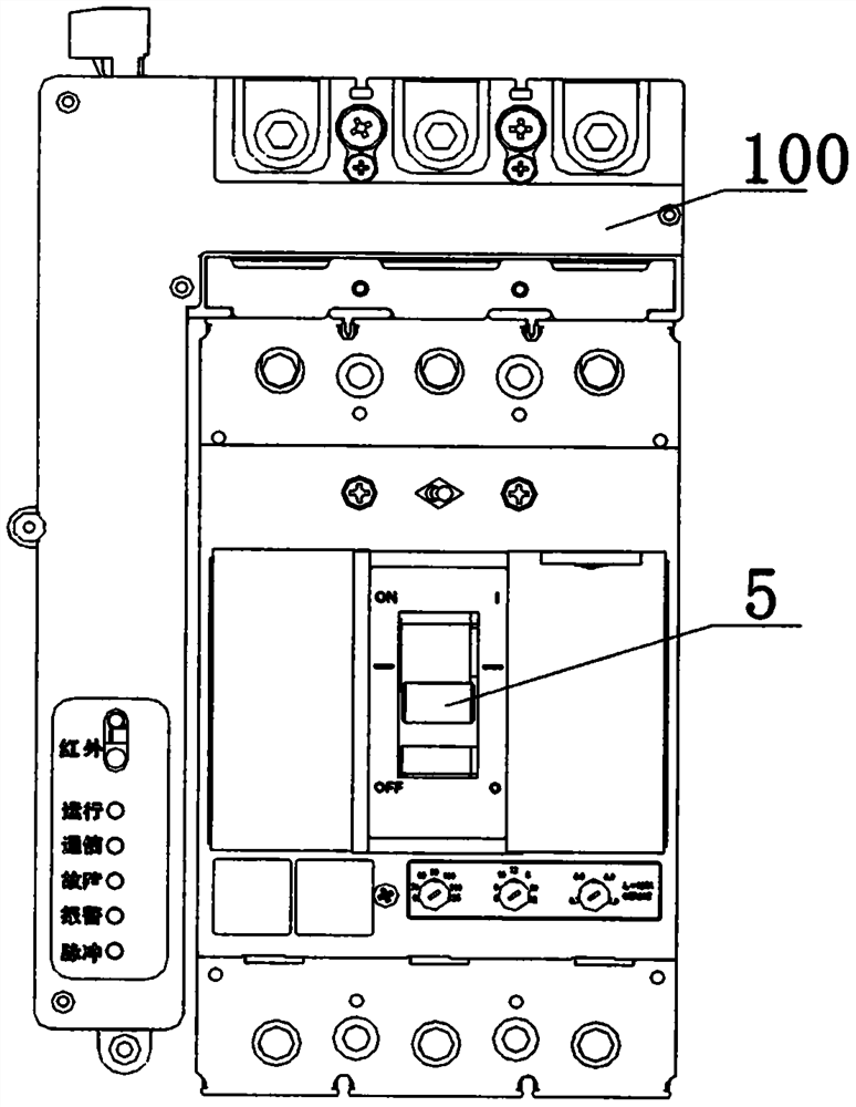
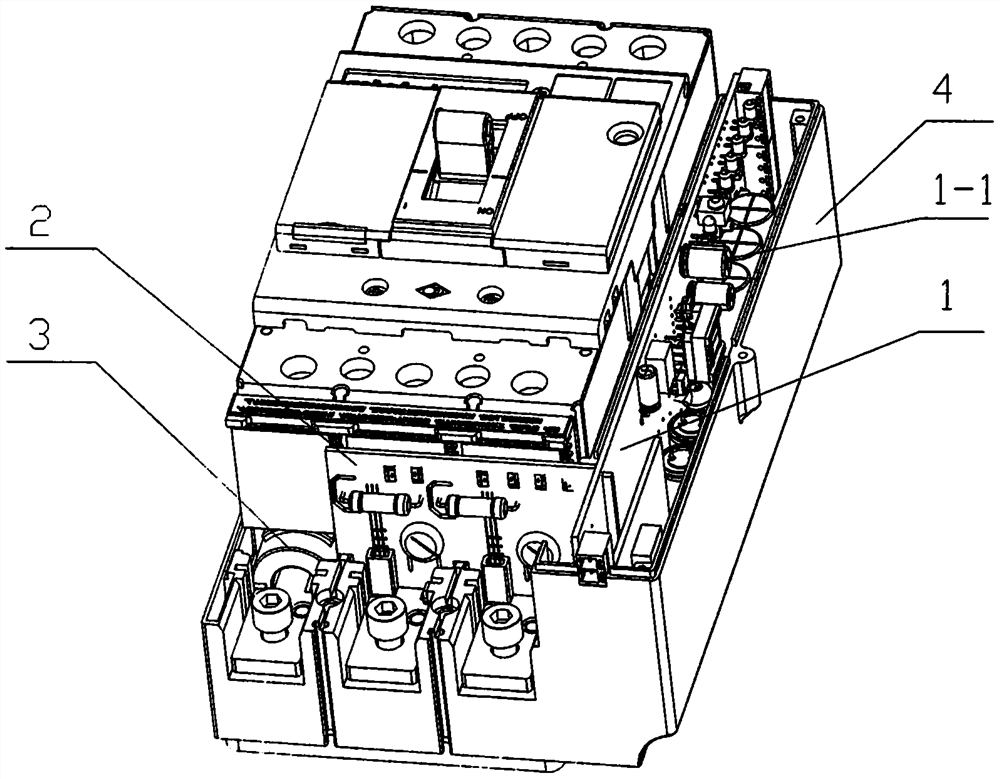
[0032] Such as figure 1, is a schematic diagram of a current monitoring device. This embodiment discloses a current monitoring device 100. The current monitoring device 100 incl...


PUM


Abstract

A current monitoring device disclosed by the present invention comprises an electronic controller (1), at least one voltage acquisition module (2), at least one current acquisition module (3) and an insulating shell (4); the electronic controller (1), the voltage acquisition module (2) and the current acquisition module (3) are arranged in the insulating shell (4), and the voltage acquisition module (2) provides a voltage signal and a power supply for the electronic controller (1); and the current acquisition module (3) provides a current signal for the electronic controller (1); the electronic controller (1) judges whether an overload fault or a short-circuit fault occurs in a current loop according to the characteristics of a normal voltage signal, a sudden voltage loss signal, a normal current signal and a distortion current signal which occur within a period of time, and the electronic controller (1) records and gives an alarm or outputs an alarm signal to the outside in a communication mode (11).

Description

technical field [0001] The invention relates to the field of power distribution monitoring, in particular to a current monitoring device installed at the inlet end of a switch of a distribution branch circuit. Background technique [0002] As the State Grid continues to promote the ubiquitous power Internet of Things plan, various products in the power system are constantly being upgraded and upgraded, and the renovation project of the existing stock metering box is becoming increasingly urgent. Considering the large stock base of the existing station area and the need to control the cost of renovation, an intelligent monitoring device is installed on the ordinary thermal-magnetic incoming line switch or isolating switch of the existing metering box to realize intelligent transformation and improve the monitoring level of the station area. In the Internet of Things technology, functions such as topology identification, line loss management, power theft monitoring, and load i...

Claims


Application Information

Patent Timeline
IPC IPC(8): G01R19/165G01R31/52G01R31/08
CPCG01R19/16547G01R31/086
Inventor 南寅董郁朱金保李勇章龙吕毅华吴国亮于雷谷春雷张小霞张晓璟
Owner TIANJIN SVRUI INTELLIGENT ELECTRICAL CO LTD
Learn More