
Mixer for U-shaped tail gas after-treatment device and U-shaped tail gas after-treatment device

A tail gas post-treatment and mixer technology, which is applied in exhaust devices, mufflers, gas passages, etc., can solve problems such as low SCR conversion efficiency, unfavorable urea pyrolysis and hydrolysis, and short mixer strokes, etc., to reduce crystallization risk, increase the gas flow rate, and improve the effect of heat utilization efficiency

Pending Publication Date: 2021-09-28
无锡恒和环保科技有限公司
View PDF0 Cites 3 Cited by
  • Summary
  • Abstract
  • Description
  • Claims
  • Application Information

AI Technical Summary

Problems solved by technology

[0003] At present, for the large-displacement U-shaped post-processor with the DOC inlet end located below the catalytic converter, there are two main nozzle arrangements: 1. The nozzle position is arranged at the outlet end of the DPF unit, and the mixing stroke is long. The main disadvantage is urea easy to crystallize
2. The nozzle is located above the inlet of the mixer, and the applicable space is compact. The disadvantage is that the stroke of the mixer is short
[0004] In the above two structures, it is not conducive to the pyrolysis and hydrolysis of urea, and it is easy to crystallize, which leads to the failure of low SCR conversion efficiency.

Method used


Image

  • Mixer for U-shaped tail gas after-treatment device and U-shaped tail gas after-treatment device
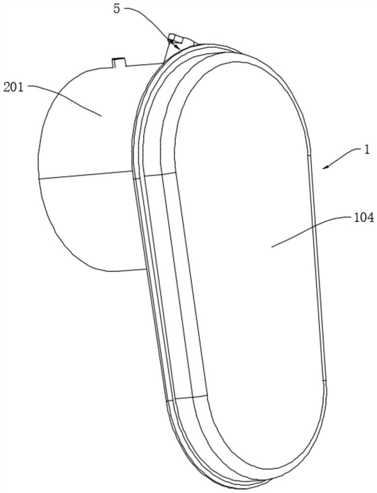
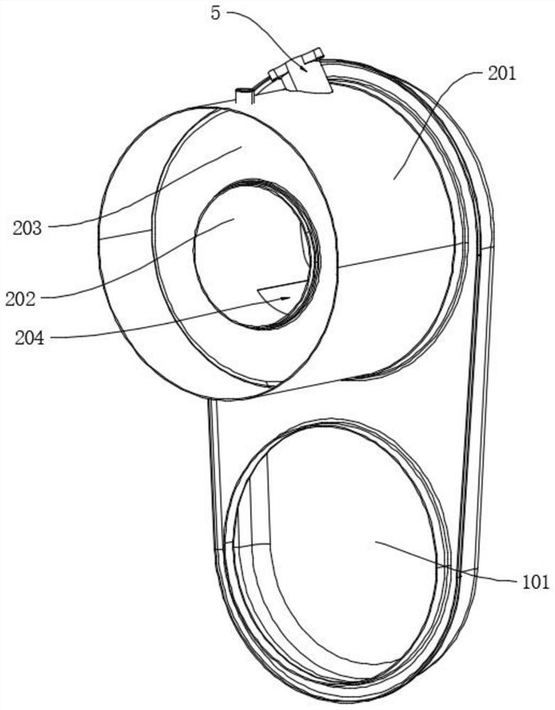
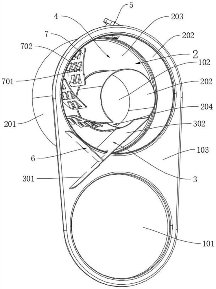
  • Mixer for U-shaped tail gas after-treatment device and U-shaped tail gas after-treatment device
  • Mixer for U-shaped tail gas after-treatment device and U-shaped tail gas after-treatment device

Examples


Embodiment Construction

[0023] The technical solution of the present invention will be clearly and completely described below in conjunction with the accompanying drawings. The relevant components in the invention are not drawn according to the number, shape and size of the components in actual implementation. The type, quantity and proportion of each component in actual implementation can be changed arbitrarily, and the layout of the components may also be changed for complex.

[0024] See Figure 1 to Figure 3 , a mixer for a U-shaped exhaust gas aftertreatment device according to the present invention includes a mixer housing 1, the mixer housing includes an air inlet 101 connected to a DPF unit and an air outlet 102 connected to an SCR unit, and the mixer housing A mixing chamber 2 is provided in the body, a deflector 3 is provided in the mixer housing 1 near the air inlet 101, a gas mixing channel 4 is provided in the mixing chamber 2, and a urea nozzle 5 is provided on the gas mixing channel 4...


PUM


Abstract

The invention provides a mixer for a U-shaped tail gas after-treatment device and the U-shaped tail gas after-treatment device comprising the mixer. The heating path of air flow to urea is prolonged, the heat utilization efficiency of tail gas is improved, the urea fully absorbs heat and exerts the heat, the risk of urea crystallization is effectively reduced, the mixer comprises a mixer shell, the mixer shell comprises a gas inlet connected to a DPF unit and a gas outlet connected to an SCR unit, a mixing cavity is formed in the mixer shell, the mixer is characterized in that a flow guide plate is arranged at the position, close to the gas inlet, in the mixer shell, a gas mixing channel is formed in the mixing cavity, a urea nozzle is arranged on the gas mixing channel, and gas entering from the gas inlet is guided by the flow guide plate to enter the gas mixing channel, and is discharged from the gas outlet after flowing through the gas mixing channel.

Description

technical field [0001] The invention relates to the technical field of exhaust gas post-treatment devices of diesel engines, in particular to a mixer for a U-shaped exhaust gas post-treatment device and a U-shaped exhaust gas post-treatment device. Background technique [0002] With the implementation of the national six-stage emission regulations, the country's requirements for engine emission limits are becoming more and more stringent. At present, due to the limited layout space of the whole vehicle, most U-shaped post-processing has very strict requirements on the appearance structure and space size of the entire post-processing, so the layout space for the mixer is also very limited. [0003] At present, for the large-displacement U-shaped post-processor with the DOC inlet end located below the catalytic converter, there are two main nozzle arrangements: 1. The nozzle position is arranged at the outlet end of the DPF unit, and the mixing stroke is long. The main disadva...

Claims


Application Information

Patent Timeline
Patent Type & Authority Applications(China)
IPC IPC(8): F01N3/28F01N13/00
CPCF01N3/2892F01N13/001F01N2470/00Y02A50/20
Inventor 杨延相谈秉乾何瑞吕柏禹
Owner 无锡恒和环保科技有限公司
Learn More