
Automatic stamping machine

An automatic stamping machine and seal technology, applied in mechanical equipment, vibration suppression adjustment, printing, etc., to achieve the effect of ensuring clarity, convenient use, and improving accuracy

Pending Publication Date: 2021-09-28
PANZHIHUA UNIV
View PDF0 Cites 3 Cited by
  • Summary
  • Abstract
  • Description
  • Claims
  • Application Information

AI Technical Summary

Problems solved by technology

[0003] The technical problem to be solved by the present invention is that the existing stamping machine adopts gears and racks to stamp, which results in high production cost due to high manufacturing precision.

Method used


Image

  • Automatic stamping machine
  • Automatic stamping machine
  • Automatic stamping machine

Examples


Embodiment Construction

[0020] The present invention will be further described below in conjunction with the accompanying drawings.

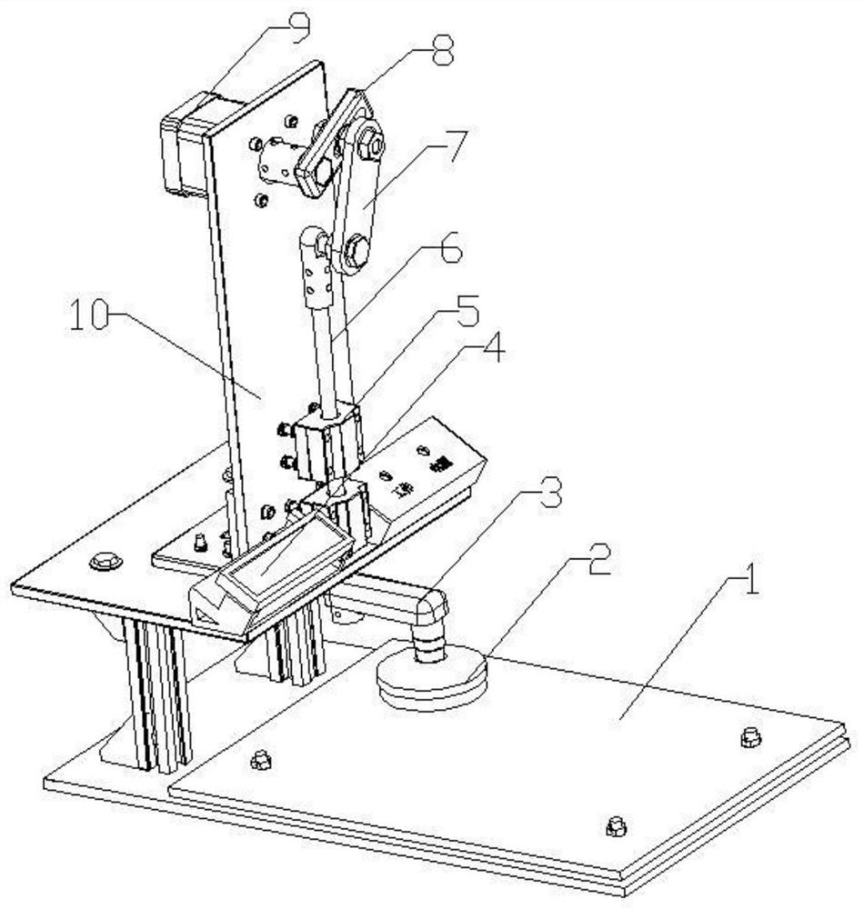
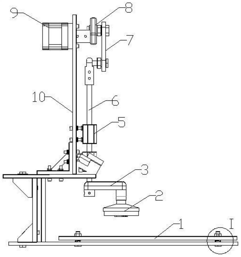
[0021] Such as Figure 1 to Figure 4 As shown, the automatic stamping machine of the present invention includes a frame 10, a rotating member 9, an intermediate rod 7, and a connecting rod 6. The rotating member 9 is arranged on the frame 10, and one end of the intermediate rod 7 is connected to the output shaft of the rotating member 9 , the other end is hinged with the connecting rod 6, the other end of the connecting rod 6 can be connected with the stamp 2, and the rotary member 9 is turned so that the stamp 2 can move up and down. Those skilled in the art can understand that the frame 10 of the device is mainly used to support the whole device, so its structure can be determined according to the implementation requirements. The rotating member 9 is installed on the frame 10, and the rotating member 9 mainly provides a source of power, so the rotating member 9 may ...


PUM


Abstract

The invention discloses an automatic stamping machine, and belongs to the technical field of seal auxiliary equipment. The automatic stamping machine comprises a machine frame(10), a rotating part (9), a middle rod (7) and a connecting rod (6), the rotating part (9) is arranged on the machine frame(10), one end of the middle rod (7) is connected with an output rotating shaft of the rotating part (9), the other end of the middle rod (7) is connected with the connecting rod (6), the other end of the connecting rod (6) can be connected with a seal (2), and the rotating part (9) is rotated to enable the seal (2) to move up and down. According to the device, the seal (2) can move up and down by rotating the rotating part (9) through a crank connecting rod mechanism composed of the rotating part (9), the middle rod (7) and the connecting rod (6), and the purpose of automatic stamping is achieved. The problem that an existing stamping machine achieves stamping through a gear and a rack, manufacturing precision is high, and production cost is high is solved.

Description

technical field [0001] The invention discloses an automatic stamping machine, which belongs to the technical field of seal auxiliary equipment. Background technique [0002] Stamping refers to affixing a seal to a document. For a small number of documents, manual stamping is often used. However, when a large number of documents are stamped, manual stamping is labor-intensive, and it is often completed with the help of a stamping machine. And what its mechanism principle of current stamping machine adopts is the rack and pinion transmission mechanism, drives the gear to rotate by motor rotation, thereby has realized the up and down reciprocating motion of the rack that connects seal, has finished the action of stamping. Since stamping requires the seal to be operated straight up and down, the existing stamping machine requires high precision of gear and rack cooperation, resulting in high production costs for the entire equipment. Contents of the invention [0003] The tec...

Claims


Application Information

Patent Timeline
Patent Type & Authority Applications(China)
IPC IPC(8): B41K3/04B41K3/62F16F15/067
CPCB41K3/04B41K3/62F16F15/067
Inventor 刘财勇王祥宇张佩尧翟纯健
Owner PANZHIHUA UNIV
Learn More