Dehumidification device for power distribution box
A distribution box and box technology, applied in substation/distribution device housing, substation/switchgear cooling/ventilation, substation/switch layout details, etc., can solve problems such as short circuit, easy accumulation of dust, etc., to save manpower resources, improve quality, reduce impact
- Summary
- Abstract
- Description
- Claims
- Application Information
AI Technical Summary
Problems solved by technology
Method used
Image
Examples
Embodiment 1
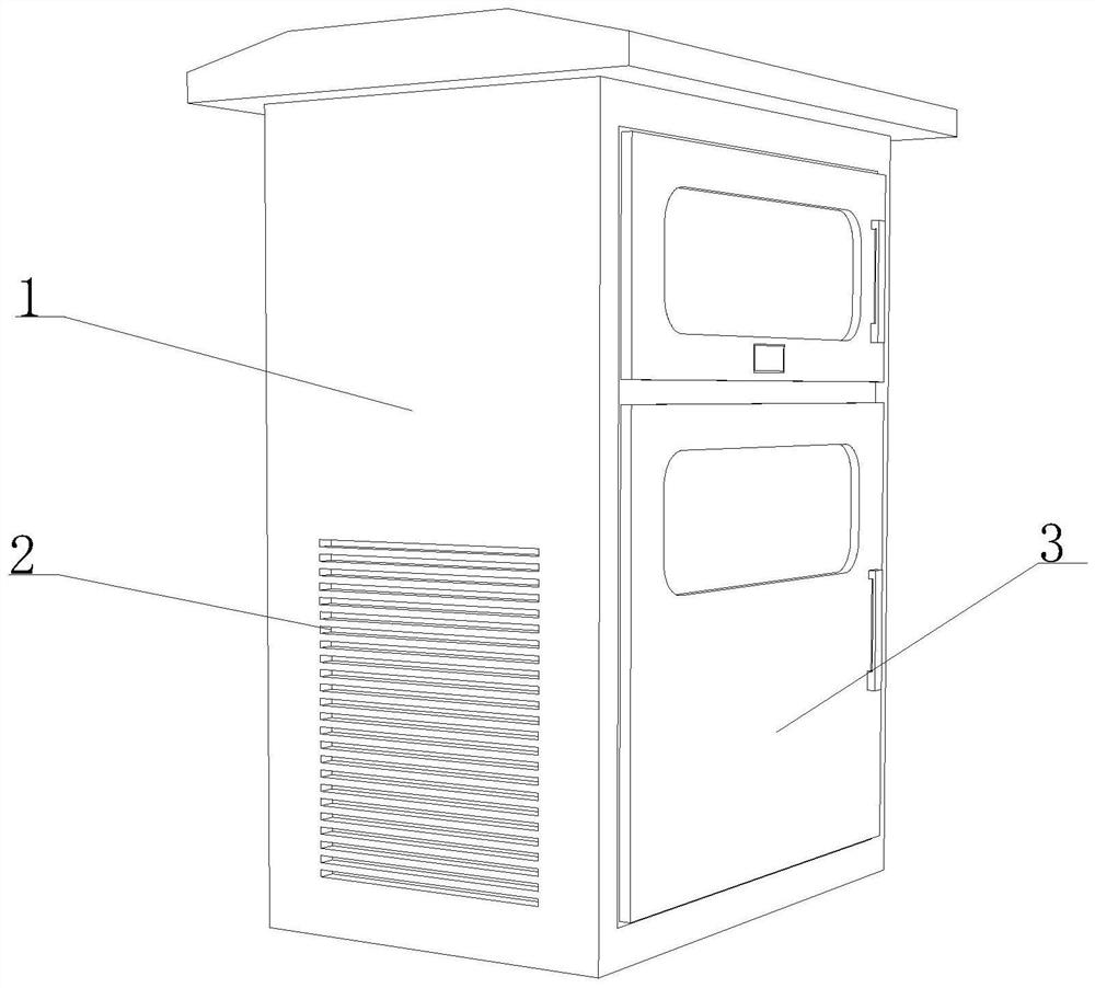
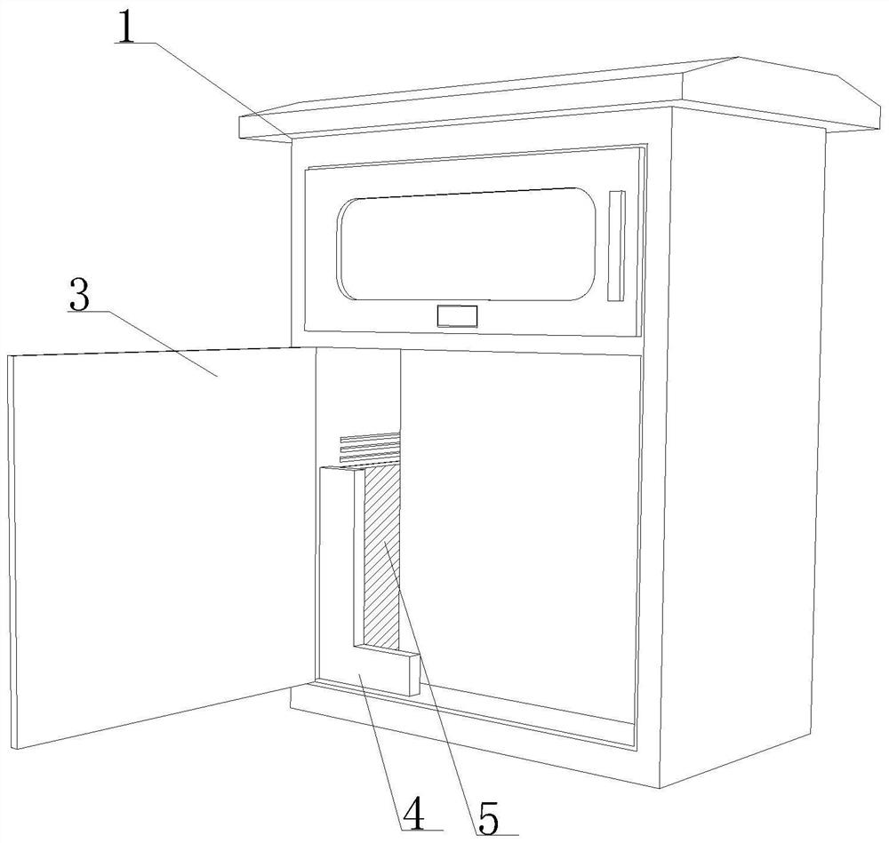
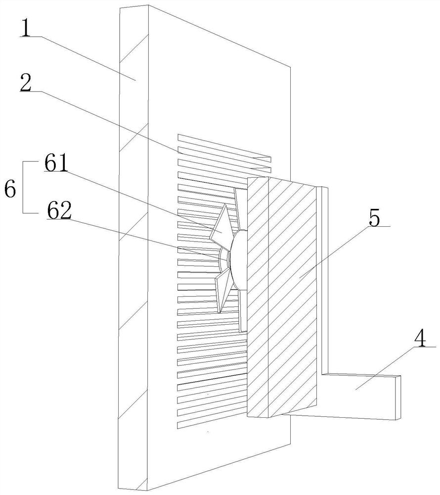
[0035] Such as Figure 1-8 As shown, the present invention provides a dehumidification device for a distribution box, including a distribution box 1 and a circulation groove 2 opened on its right side, a movable sealing door 3 is arranged on the front of the distribution box 1, and the distribution box A connecting arm 4 is arranged on the bottom of the inner cavity of the body 1 and to the right, and a dehumidification mechanism 5 is arranged on the inner side of the connecting arm 4, and a flow guide mechanism 6 is arranged on the right side of the inner cavity of the power distribution box body 1, and the flow guide mechanism 6 is located in the dehumidification mechanism. On the right side of 5, when the dehumidification device for distribution box is in use, the inner wall of the distribution box 1 is provided with power components. Adjacent to the flow tank 2 , the dehumidification mechanism 5 is located on the right side of the flow guiding mechanism 6 .
[0036] Furth...
Embodiment 2
[0039] Such as Figure 1-8 As shown, on the basis of Embodiment 1, the present invention provides a technical solution: preferably, the curved processing frame 56 includes a filter plate 561 and an outer moisture-absorbing plate 562, and the ends of the filter plate 561 and the outer moisture-absorbing plate 562 Through the detachable connection provided with the connecting beam 7, the outer moisture-absorbing plate 562 is close to the circulation groove 2 opened on the side of the distribution box 1, which can effectively dehumidify the air entering the distribution box 1 from the external environment.
[0040] Further, the top and bottom of the inner surface of the filter plate 561 are provided with a first elastic frame 8, and the inner side of the first elastic frame 8 is fixedly connected with the inner surface of the filter plate 561 by being provided with an outer transmission rod 9, and the outer moisture-absorbing plate 562 The top and bottom of the inner surface of t...
Embodiment 3
[0042] Such as Figure 1-8 As shown, on the basis of Embodiment 1, the present invention provides a technical solution: preferably, the inner top and bottom of the filter plate 561 and the outer moisture-absorbing plate 562 are movably connected with arc-shaped leaves 13 through a connecting frame, The curved leaves 13 are symmetrically arranged. The curved leaves 13 all include metal cooling blocks 131 and deodorizing plates 132. The metal cooling blocks 131 are provided with deodorizing plates 132 near the side of the filter plate 561. The metal cooling blocks 131 and The deodorizing plate 132 adopts sodium-potassium alloy and bamboo charcoal plate as raw materials respectively, which can effectively cool and deodorize the air passing through the filter plate 561 and entering the inside of the filter plate 561 and the outer moisture-absorbing plate 562.
[0043] Further, the surface of the dehumidification plate 51 is uniformly provided with a rectangular groove 14, and the ...
PUM
 Abstract
Description
Claims
Application Information
 - Generate Ideas
- Intellectual Property
- Life Sciences
- Materials
- Tech Scout
- Unparalleled Data Quality
- Higher Quality Content
- 60% Fewer Hallucinations
Browse by: Latest US Patents, China's latest patents, Technical Efficacy Thesaurus, Application Domain, Technology Topic, Popular Technical Reports.
© 2025 PatSnap. All rights reserved.Legal|Privacy policy|Modern Slavery Act Transparency Statement|Sitemap|About US| Contact US: help@patsnap.com


