Multi-frequency antenna device and mobile terminal

An antenna device, multi-frequency antenna technology, applied in the field of communication

Pending Publication Date: 2021-09-24
BLACKSHARK TECH NANCHANG CO LTD
View PDF4 Cites 0 Cited by
  • Summary
  • Abstract
  • Description
  • Claims
  • Application Information

AI Technical Summary

Problems solved by technology

[0004] In order to overcome the above-mentioned technical defects, the object of the present invention is to provide a multi-frequency antenna device and a mobile terminal, which are used to solve the problem of realizing multi-band and multi-mode antennas on the same antenna to meet the needs of use

Method used


Image

  • Multi-frequency antenna device and mobile terminal
  • Multi-frequency antenna device and mobile terminal
  • Multi-frequency antenna device and mobile terminal

Examples


Embodiment 1

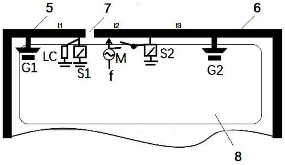
[0046] Embodiment 1: This embodiment provides a multi-frequency antenna device, refer to figure 1 , used to design a multi-frequency multi-mode integrated antenna that realizes full-band LTE, WIFI5G, Sub6G and other functions in response to the increasing frequency band requirements of antennas and the increasingly tight antenna design space. The antenna can use metal middle frames, Metal back shell, LDS / FPC, etc., among which figure 1 The middle area 2 is the main board, and the dark wire frame 1 around it is the metal frame of the mobile phone (or metal back shell, LDS, FPC, etc.), specifically, including the first antenna radiation part 5 and the second antenna radiation part 6; An antenna slit 7 is provided between the first antenna radiating portion 5 and the second antenna radiating portion 6; preferably, in order to further reduce the mutual interference between the first antenna radiating portion 5 and the second antenna radiating portion 6, the The width of the anten...

Embodiment 2

[0055] Embodiment 2: This embodiment provides a mobile terminal, refer to figure 1 , including: a main board 8, a metal frame wrapping the main board 8 (in the figure coincident with the first radiating part 5 and the second radiating part 6) and the antenna device described in one of the above-mentioned embodiments; the antenna device can be It is implemented by using a metal middle frame, a metal rear case, LDS / FPC, etc., and the antenna device is distributed on the top, bottom or side metal frame of the mobile terminal.

[0056] Smart terminals can be implemented in various forms. For example, terminals described in the present invention may include smart terminals such as mobile phones, smart phones, notebook computers, PDAs (Personal Digital Assistants), PADs (Tablet Computers), PMPs (Portable Multimedia Players), navigation devices, etc., and such as Stationary terminal for digital TV, desktop computer, etc. In the following, it is assumed that the terminal is an intel...


PUM

PropertyMeasurementUnit
Gap widthaaaaaaaaaa

Abstract

The invention provides a multi-frequency antenna device and a mobile terminal, and relates to the technical field of communication. The multi-frequency antenna device comprises a first antenna radiation part, a second antenna radiation part and an antenna slot; a first grounding point and a second grounding point are respectively arranged at one ends, far away from the antenna slot, of the first antenna radiation part and the second antenna radiation part; and a first antenna switch and a filter network are connected between the first antenna radiation part and the antenna slot. The second antenna radiation part is connected with a feeding point, a second antenna switch is connected between the feeding point and the second grounding point, and the feed point is provided with a feed circuit matching unit. The switching between an LTE low-frequency resonant mode and an LTE intermediate-frequency resonant mode is realized through the switching of the second antenna switch, the switching between an LTE high-frequency resonant mode and an LTE intermediate-frequency resonant mode is realized through the first antenna switch, and after the first antenna switch is switched to the LTE high-frequency resonant mode, and a WIFI 5G / Sub6G resonant mode is realized through the filter network and the feed circuit matching unit, so that the problem that a multi-band multi-mode antenna is realized on the same antenna to meet the use requirements is solved.

Description

technical field [0001] The present invention relates to the technical field of communication, in particular to a multi-frequency antenna device and a mobile terminal. Background technique [0002] Electronic products with wireless communication functions, such as notebook computers, personal digital assistants (Personal Digital Assistant), etc., transmit or receive radio waves through antennas to transmit or exchange radio signals, and then access wireless networks. Therefore, in order to allow users to access wireless communication networks more conveniently, the bandwidth of an ideal antenna should be increased as much as possible within the allowable range, while the size should be reduced as much as possible to match the trend of shrinking electronic products. In addition, with the continuous evolution of wireless communication technology, the number of antennas configured on electronic products may increase. [0003] With the gradual development of next-generation mobi...

Claims


Application Information

Patent Timeline
IPC IPC(8): H01Q1/24H01Q1/36H01Q1/48H01Q1/50H01Q5/10H01Q5/28H01Q5/314H01Q5/335H01Q5/50
CPCH01Q1/242H01Q1/36H01Q1/50H01Q1/48H01Q5/10H01Q5/28H01Q5/314H01Q5/335H01Q5/50Y02D30/70
Inventor 张进锋王洪裕
Owner BLACKSHARK TECH NANCHANG CO LTD
Why Eureka
Try Eureka