A plate-belt composite bulk material ship loader
A technology for ship loaders and materials, applied in the direction of conveyors, loading/unloading, conveyor objects, etc., which can solve problems such as pipeline blockage and inability to screen bulky materials
- Summary
- Abstract
- Description
- Claims
- Application Information
AI Technical Summary
Problems solved by technology
Method used
Image
Examples
Embodiment 1
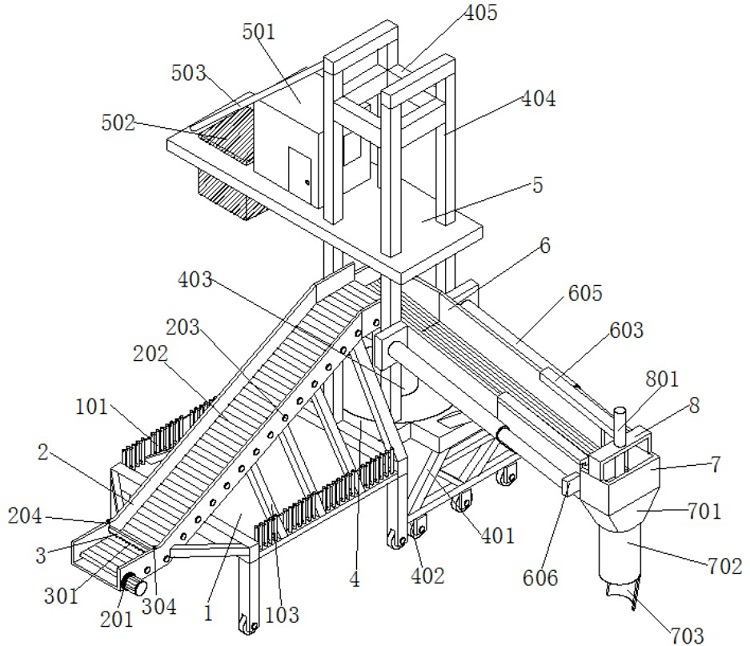
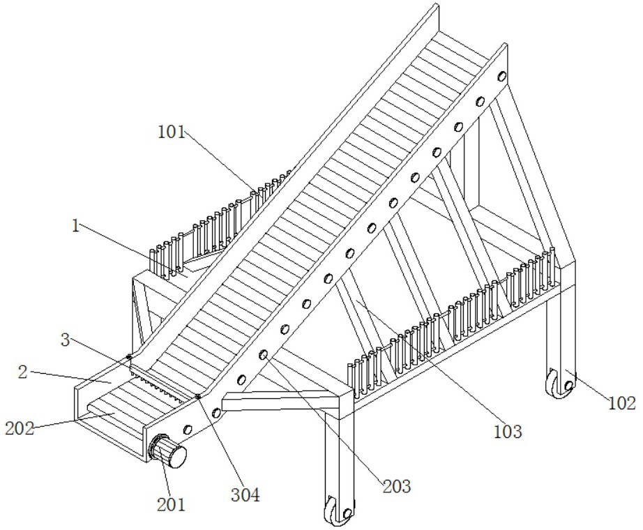
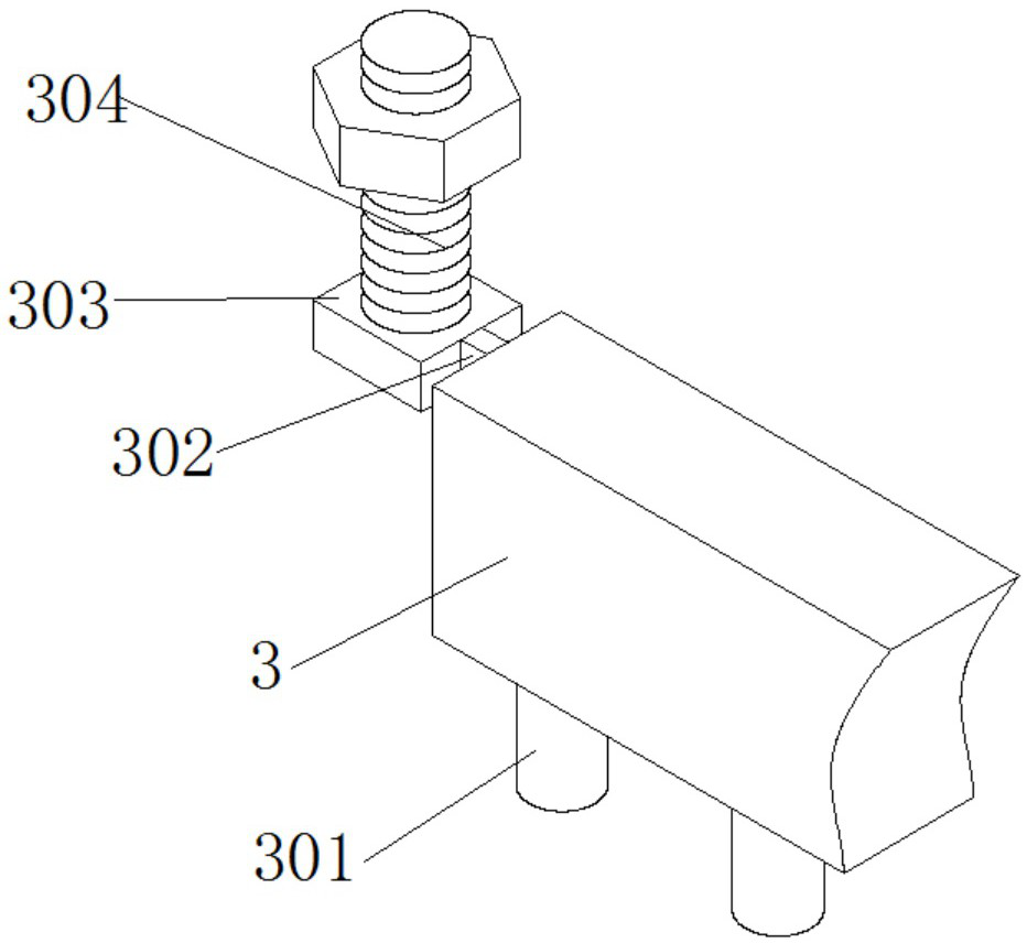
[0043] Such as figure 1 , Figure 5 and Image 6 As shown, a board-strip composite bulk material ship loader includes a bed frame 1, a transportation board frame 2 and a strip block 3, the top of the bed frame 1 is equipped with a transportation board frame 2, and the front and rear inner walls of the transportation board frame 2 are installed There is a long block 3, a main body chassis 4 is installed on the outer wall of one side of the bed frame 1, and a column 403 is installed on the top of the main body chassis 4;
[0044] Specifically, the bed frame 1 is used to install the transport panel frame 2, and the transport panel frame 2 can rotate the motor 201, the conveyor belt 202 and the roller 203 and other components to facilitate the transportation of materials, and the long strip 3 is used for multiple groups of intercepting rods The combined installation of 301, the main body chassis 4 is used to install the main parts of the device, and the cylinder 403 can facilita...
Embodiment 2
[0051] Such as Figure 7 As shown, the top of the extension frame 602 is equipped with a clamping plate 603, and the inner wall of the clamping plate 603 is attached to the inner wall of the conveying frame 601, and the top of the main chassis 4 is evenly equipped with four groups of vertical bars 404 arranged in a square shape, two of which A platform board 5 is installed on the front side of the set of vertical bars 404 , and the back side of the platform board 5 runs through the interior of the other two groups of vertical bars 404 .
[0052] Specifically, the clamping plate 603 can increase the connection between the extension frame 602 and the conveying frame 601, and it can be engaged on the plates on both sides of the conveying frame 601 to prevent the extension frame 602 from falling down from the outer surface of the conveying frame 601. The vertical rods 404 can be used to install the platform board 5, and the outer walls of one side of the four groups of vertical ro...
Embodiment 3
[0058] Such as Figure 8 As shown, a rotating plate 9 is installed on the bottom of the cylinder 802, an annular plate is installed on the top of the rotating plate 9, and the inner wall of the annular plate is attached to the inner wall of the annular groove 803, and a servo motor 901 is installed on the top of the rotating plate 9. The output end of motor 901 is equipped with rotating shaft, and the bottom of rotating shaft runs through the inside of rotating plate 9, and the bottom of rotating shaft is equipped with and pokes material bar 902, and the both sides outer walls of poking material bar 902 are all equipped with expander plate 903.
[0059] Specifically, the rotating plate 9 provides a stable installation position for the servo motor 901. When the servo motor 901 is started, the rotating shaft installed at the output end of the servo motor 901 can rotate according to the set speed. The side plate 903 can follow the rotation. When it rotates, the material bar 902 c...
PUM
 Abstract
Description
Claims
Application Information
 - Generate Ideas
- Intellectual Property
- Life Sciences
- Materials
- Tech Scout
- Unparalleled Data Quality
- Higher Quality Content
- 60% Fewer Hallucinations
Browse by: Latest US Patents, China's latest patents, Technical Efficacy Thesaurus, Application Domain, Technology Topic, Popular Technical Reports.
© 2025 PatSnap. All rights reserved.Legal|Privacy policy|Modern Slavery Act Transparency Statement|Sitemap|About US| Contact US: help@patsnap.com


