A kind of printing equipment for capacitor processing

A capacitor processing and printing equipment technology, applied in printing, printing machine, rotary printing machine and other directions, can solve the problems of low efficiency and high production cost, and achieve the effect of high efficiency, low production and use cost, and low energy consumption

Active Publication Date: 2022-04-19
东莞市普隆电子有限公司
View PDF6 Cites 0 Cited by
  • Summary
  • Abstract
  • Description
  • Claims
  • Application Information

AI Technical Summary

Problems solved by technology

[0004] The purpose of the present invention is to solve the problems of high production cost and low efficiency in the prior art, and propose a printing equipment for capacitor processing

Method used


Image

  • A kind of printing equipment for capacitor processing
  • A kind of printing equipment for capacitor processing
  • A kind of printing equipment for capacitor processing

Examples


Embodiment 1

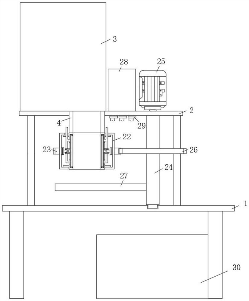
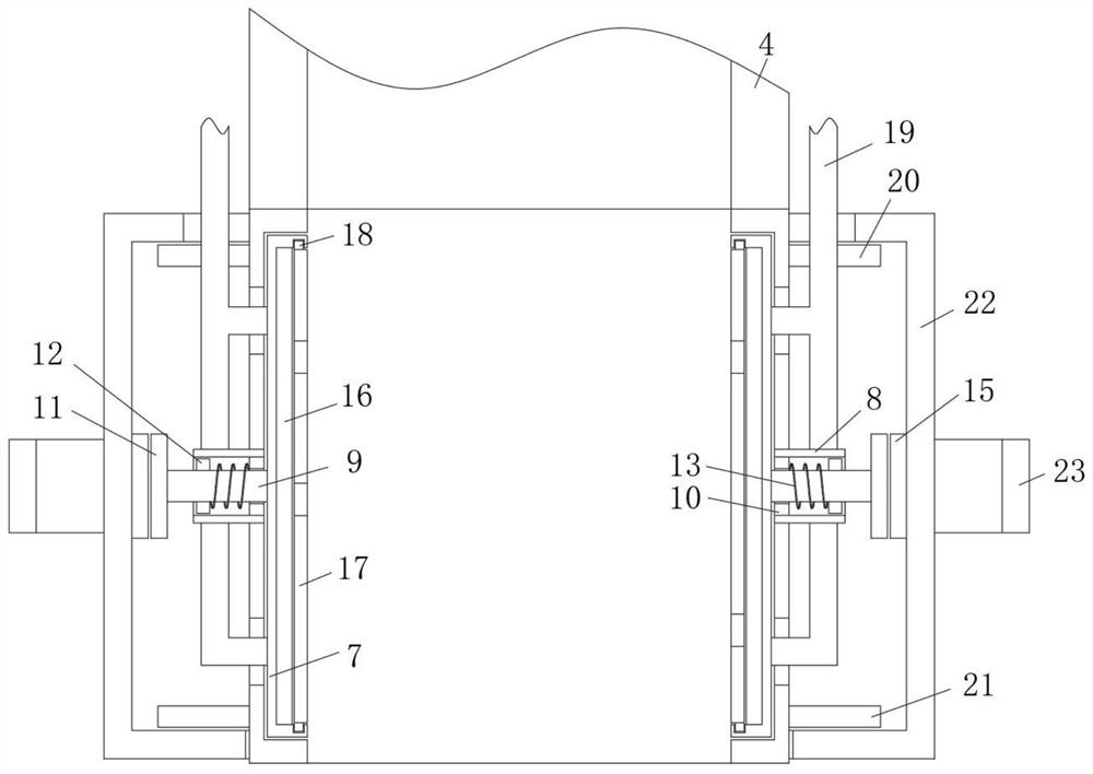
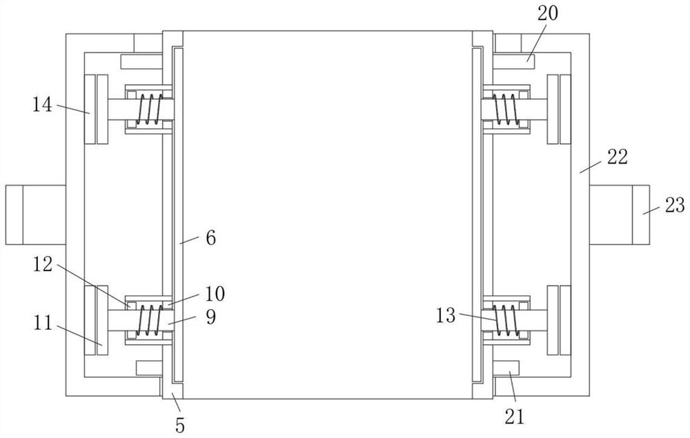
[0029] refer to Figure 1-4 , a kind of printing equipment for capacitor processing, comprising a workbench 1, the top of the workbench 1 is fixed with a stand 2, the top of the stand 2 is equipped with a feeding tray 3, and the bottom outlet of the feeding tray 3 is connected with a discharge pipe 4. The bottom of the feeding pipe 4 is provided with a printing mechanism. The printing mechanism includes a processing end pipe 5 fixedly connected to the bottom of the feeding pipe 4. The body of the processing end pipe 5 is provided with side grooves 1 and 2, side groove 1 and There are multiple side slots 2, and they are set at equal intervals. A capacitor clamping mechanism is arranged in the side slot 1, and a printing mechanism is arranged in the side slot 2. The capacitor clamping mechanism includes a positioning bead vertically arranged in the side slot 1. 6. The printing mechanism includes printing strips 7 vertically arranged in the second side slot. A placement groove is...

Embodiment 2

[0032] Such as Figure 1-4 As shown, this embodiment is basically the same as Embodiment 1. Preferably, the ink supply mechanism includes a liquid storage tank 28 fixedly installed on the top side of the platform 2, and the vertical side of the printing strip 7 is fixedly communicated with a liquid inlet pipe 19 for feeding The top of the liquid pipe 19 communicates with the bottom of the liquid storage tank 28 , and the pipe body of the liquid inlet pipe 19 is provided with a valve 29 .

[0033]In this embodiment, the arrangement of the ink supply mechanism completes the replenishment and control of the amount of ink in the liquid storage sliver 16 and ensures the continuity of printing.

Embodiment 3

[0035] Such as Figure 1-4 As shown, this embodiment is basically the same as Embodiment 1. Preferably, the top inner wall and the bottom inner wall of the printing strip 7 are provided with card slots. card slot.

[0036] In this embodiment, when printing capacitors with different contents, select the corresponding hollowed-out printed board 17 for replacement and installation. Can.


PUM


Abstract

The invention discloses a printing device for capacitor processing, which comprises a workbench, the top of the workbench is fixed with a platform, the top of the platform is equipped with a feeding tray, and the bottom outlet of the feeding tray is connected to a The feeding pipe, the bottom of the feeding pipe is provided with a printing mechanism, and the printing mechanism includes a processing end pipe fixedly connected to the bottom end of the feeding pipe, and the pipe body of the processing end pipe is provided with a side groove 1 and a side groove 2, There are a plurality of side slots 1 and 2 respectively, and they are arranged equidistantly. A capacitor holding mechanism is arranged in side slot 1, and a printing mechanism is arranged in side slot 2. The capacitor holding mechanism includes vertically arranged The positioning bead in the first slot, the printing mechanism includes a printing bar vertically arranged in the second side slot. The invention has good printing effect on capacitors, high efficiency, low energy consumption, low production and use costs, small footprint, strong versatility and convenient use, and meets the needs of people in production and life.

Description

technical field [0001] The invention relates to the technical field of capacitor processing equipment, in particular to printing equipment for capacitor processing. Background technique [0002] Two conductors that are close to each other, with a layer of non-conductive insulating medium in between, constitute a capacitor. A capacitor stores charge when a voltage is applied between its two plates. The capacitance of a capacitor is numerically equal to the ratio of the amount of charge on a conductive plate to the voltage between the two plates. The basic unit of capacitance of a capacitor is farad (F). Capacitive elements are usually represented by the letter C in circuit diagrams. [0003] Existing capacitors need to be printed on the appearance, LOGO, model, date, etc. before leaving the factory. In this step, the existing equipment is progressive. After the rotating mechanism completes the turning over, the capacitor is moved to the bottom of the previous printing mec...

Claims


Application Information

Patent Timeline
Patent Type & Authority Patents(China)
IPC IPC(8): B41F17/24
CPCB41F17/24B41P2217/50B41P2217/60
Inventor 叶宝华张海波范鹏元姜礼
Owner 东莞市普隆电子有限公司
Why Eureka
Try Eureka