
Horizontal position welding method and system for austenitic stainless steel bottom-locking structure

An austenitic stainless steel, horizontal welding technology, applied in welding equipment, welding accessories, arc welding equipment, etc., can solve the problems of difficult to guarantee the penetration depth of the workpiece, poor thermal conductivity, poor structure and performance of the workpiece, etc., and achieve the reduction of welding process requirements , reduce welding cost, improve the effect of forming quality

Active Publication Date: 2021-09-24
BEIHANG UNIV
View PDF7 Cites 2 Cited by
  • Summary
  • Abstract
  • Description
  • Claims
  • Application Information

AI Technical Summary

Problems solved by technology

Affected by the poor thermal conductivity of austenitic stainless steel and the poor fluidity of the liquid molten pool, when welding the austenitic stainless steel bottom lock structure, the installation gap between the double-layer structures will affect the heat transfer of the molten pool, and the horizontal welding will also cause The heat of the molten pool is difficult to transfer to the underlying structure of the workpiece, which makes it difficult to guarantee the penetration depth of the workpiece
The application of high-energy beam welding methods such as plasma welding and laser welding is limited due to the easy instability in the installation gap of the double-layer structure, while the arc energy dispersion of the ordinary DC argon arc welding method requires a huge heat input In order to ensure sufficient penetration depth, it is very easy to cause the deterioration of the structure and performance of the workpiece, and the simple use of increasing heat input will increase the volume of the molten pool, which will cause the molten pool to collapse during horizontal welding and form undercut defects. Therefore, It is also necessary to adopt methods such as beveling and wire filling, which further increase the welding cost and welding difficulty

Method used


Image

  • Horizontal position welding method and system for austenitic stainless steel bottom-locking structure
  • Horizontal position welding method and system for austenitic stainless steel bottom-locking structure
  • Horizontal position welding method and system for austenitic stainless steel bottom-locking structure

Examples


Embodiment 1

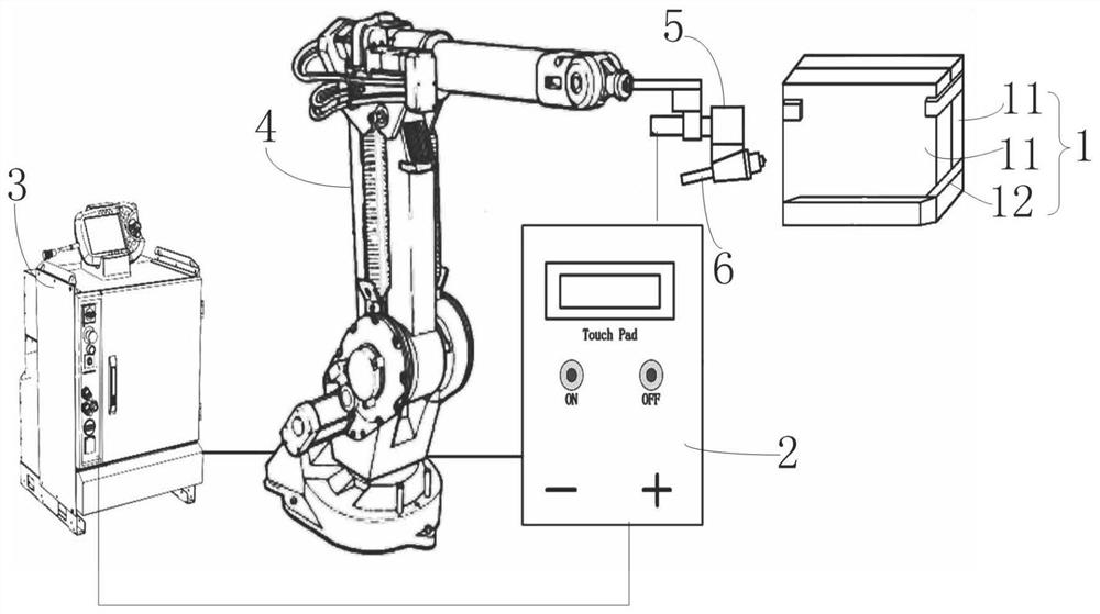
[0078] Embodiment 1, the two austenitic stainless steel layers 11 are both plate-shaped:

[0079] The working principle of the present invention is as follows:

[0080] S1, prepare the austenitic stainless steel structure 1, the austenitic stainless steel structure 1 includes: two layers of austenitic stainless steel layers 11 and a fixing tool 12, the thickness of the single-layer austenitic stainless steel layer 11 is 2 to 5 mm, and the thickness of the two-layer austenitic stainless steel layer 11 is 2 to 5 mm. The total thickness of the solid stainless steel layers 11 being closely fitted together is 4 to 10 mm, the fixing tooling 12 fixes the two austenitic stainless steel layers 11 together, and the installation gap 103 between the two austenitic stainless steel layers 11 is less than 0.2 mm;

[0081]S2, pretreatment: the welding surface of the austenitic stainless steel structure 1 is ground by means of mechanical grinding, and then wiped with alcohol and acetone solut...

Embodiment 2

[0085] Embodiment 2: The two austenitic stainless steel layers 11 are both sleeve-shaped, and the two austenitic stainless steel layers 11 are sleeved and connected (then the austenitic stainless steel layer 11 located in the internal measurement is the inner cylinder, and the austenitic stainless steel layer 11 located on the outer side is When the tensite stainless steel layer 11 is an outer cylinder, the length of the outer cylinder can reach more than 4 meters, and the flat welding process cannot be used due to the limitation of the assembly process, and only the horizontal welding position welding process can be used), the working principle is different from that of Example 1: steps In S5, the industrial robot 4 is controlled to drive the argon arc welding torch 5 to continuously approach the outermost austenitic stainless steel layer 11 (outer cylinder) until the end of the tungsten rod 6 contacts the outermost austenitic stainless steel layer On the surface of 11 (outer ...


PUM

PropertyMeasurementUnit
Thicknessaaaaaaaaaa

Abstract

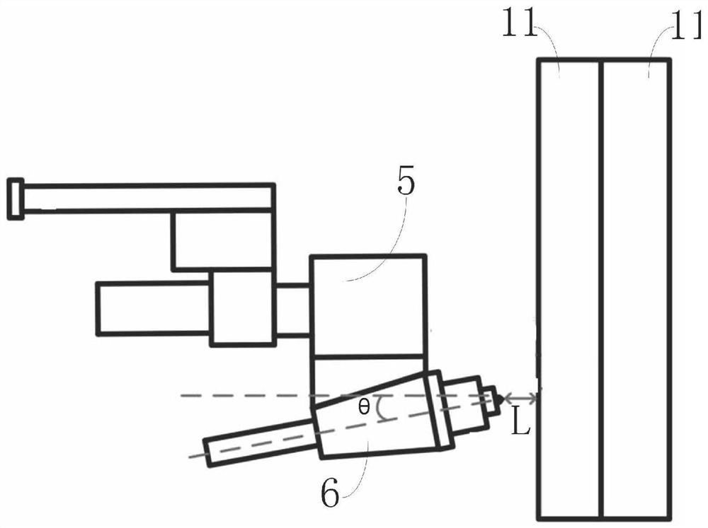
The invention discloses a horizontal position welding method for an austenitic stainless steel bottom-locking structure. The horizontal position welding method sequentially comprises the following steps of, preparing a austenitic stainless steel structure; carrying out pretreatment; installing a horizontal position welding system; adjusting the welding position, specifically, adjusting the included angle theta between the axis of a tungsten electrode bar and a horizontal line to be 10-15 degrees, and adjusting the distance L between the end of the tungsten electrode bar and the surface of the austenitic stainless steel structure to be 3-5 mm; and staring welding. The invention further discloses a horizontal position welding system for the austenitic stainless steel bottom-locking structure. A high-frequency pulse welding power source is electrically connected with a control cabinet, an industrial robot and an argon arc welding torch, the control cabinet is electrically connected with the industrial robot, the argon arc welding torch is fixed to the industrial robot, a tungsten electrode bar is fixed to the argon arc welding torch, the angle theta between the axis of the tungsten electrode bar and the horizontal line ranges from 10 degrees to 15 degrees, and the distance L between the end part of the tungsten electrode bar and the surface close to the austenitic stainless steel structure is 3-5mm. According to the horizontal position welding method and system for the austenitic stainless steel bottom-locking structure, the welding cost is reduced, the welding process requirement is lowered, and the forming quality of a welding seam is improved.

Description

technical field [0001] The invention relates to the technical field of welding methods, and more particularly to a horizontal welding method and system for austenitic stainless steel locking bottom structure. Background technique [0002] In industrial manufacturing, there are a large number of austenitic stainless steel workpieces with double-layer composite structure design. In order to ensure airtightness and reliability, such structures cannot be perforated welding, and need to use locking bottom welding. Due to environmental limitations, only the welding position of the horizontal welding position is often used when welding such workpieces. Affected by the poor thermal conductivity of austenitic stainless steel and the poor fluidity of the liquid molten pool, when welding the austenitic stainless steel lock bottom structure, the installation gap between the double-layer structures will affect the heat transfer of the molten pool, and the horizontal welding will also cau...

Claims


Application Information

Patent Timeline
IPC IPC(8): B23K9/235B23K9/167B23K9/32
CPCB23K9/235B23K9/167B23K9/32
Inventor 从保强孙雪君齐铂金贺铂昌蔡鑫祎祁泽武
Owner BEIHANG UNIV
Learn More