
Classified cyclone dust collection device with multi-stage vortex tube combination and its implementation method

A cyclone dust collection and vortex tube technology, which is applied in the separation method, the cyclone device, and the device whose axial direction of the cyclone remains unchanged, etc.

Active Publication Date: 2021-10-29
JIANGSU XINPENG HEAVY ELECTROMECHANICAL MFG
View PDF10 Cites 0 Cited by
  • Summary
  • Abstract
  • Description
  • Claims
  • Application Information

AI Technical Summary

Problems solved by technology

[0003] Patent document CN201910858911.0 proposes a cyclone separation device, including: a cyclone separation body, with a cyclone separation chamber that allows the airflow to spirally rotate around the central axis, and an air inlet, an exhaust port, and a discharge chamber that are all connected to the cyclone separation chamber. Dust port, the air inlet is located in the tangential direction of the outer circumference of the cyclone separation chamber, the exhaust port and the dust discharge port are respectively located at the opposite ends of the cyclone separation chamber in the axial direction; parts, which are respectively arranged at opposite ends of the cyclone separation body, and the collecting part has a collecting cavity communicated with the exhaust port, and the dust collecting part has a dust collecting part communicated with the dust discharge port. cavity; and an exhaust pipe, which is connected between the dust collecting part and the collecting part, and communicates with the dust collecting chamber and the collecting chamber. In this patent, only gas and dust are separated, due to dust The different types cannot be completely peeled off, and the dust cannot be classified and discharged according to the size of the dust. The fine dust is easy to rise, which affects the dust removal effect and the use effect is not good.

Method used


Image

  • Classified cyclone dust collection device with multi-stage vortex tube combination and its implementation method
  • Classified cyclone dust collection device with multi-stage vortex tube combination and its implementation method
  • Classified cyclone dust collection device with multi-stage vortex tube combination and its implementation method

Examples


Embodiment approach

[0043] In order to further and better explain the above-mentioned embodiments, the present invention also provides an embodiment, an implementation method of a classified cyclone dust collection device with a combination of multi-stage vortex tubes, comprising the following steps:

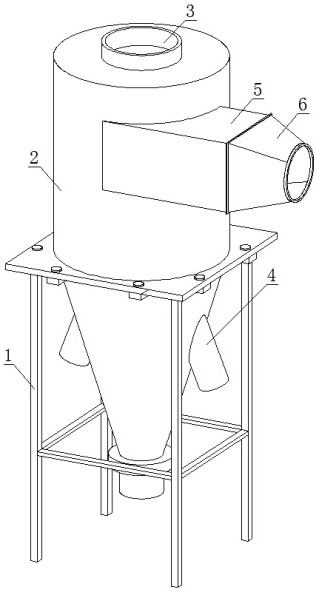
[0044] Step 1: The dust collector 2 is externally connected to a fan, and the fan is turned on to work, and the dust and gas are discharged into the interior of the dust collector 2 through the dust inlet 6;

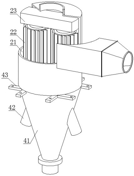
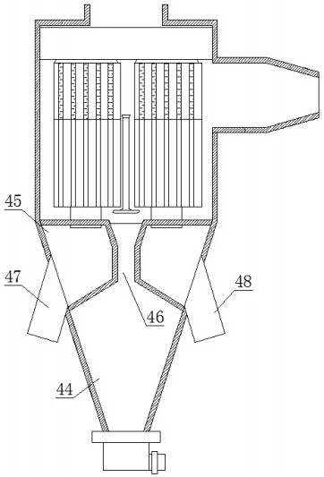
[0045] Step 2: Turn on the motor to work, the motor drives the driving wheel 22114 to rotate through the coupling 22115, so that the central shaft 22111 can rotate, and the central shaft 22111 is fixedly connected with the outer cover 2212 through the connecting plate 22112, which is convenient for the outer cover 2212 and the first worm rod 221 Rotate, the outer surface of the driving wheel 22114 is provided with a belt piece 22116, and the side of the belt piece 22116 away from the driving w...


PUM


Abstract

The invention relates to the technical field of cyclone dust collection equipment, discloses a classification type cyclone dust collection device with multi-stage vortex tube combination, and also discloses an implementation method of the classification type cyclone dust collection device with multi-stage vortex tube combination. Including the support frame and the dust collector fixedly installed on the upper end of the support frame, through the cooperation of the driving wheel, the belt and the driven wheel, the lower end of the driven wheel is fixedly installed with gear A, and one side of gear A is meshed with gear B and gear B The lower end of the gear is fixedly connected with the second worm, and through the cooperation of gear A and gear B, the second worm installed at the lower end of gear B can rotate, and the rotation direction of the first worm is opposite to that of the first worm, and the diameter of the driven wheel is larger than that of the driving wheel. Diameter, that is, the rotation speed of the second worm is lower than that of the first worm, and the whirlwind produced by the slow rotation speed is relatively weak, and can only inhale smaller particles of dust, whereas the first worm can inhale larger particles. Dust, large particles and small particles are discharged through the dust removal port respectively.

Description

technical field [0001] The patent of the present invention relates to the technical field of cyclone dust collection equipment, in particular, it relates to a classified cyclone dust collection device with a combination of multi-stage vortex tubes and its implementation method. Background technique [0002] Cyclone dust collector is a type of dust removal device. The dust removal mechanism is to make the dust-laden air flow rotate, and the dust particles are separated from the air flow by centrifugal force and collected on the wall of the device, and then the dust particles fall into the ash hopper by gravity. Each component of the cyclone dust collector has a certain size ratio. The change of each proportional relationship can affect the efficiency and pressure loss of the cyclone dust collector. Among them, the diameter of the dust collector, the size of the air inlet, and the diameter of the exhaust pipe are the main influencing factors. . [0003] Patent document CN201...

Claims


Application Information

Patent Timeline
Patent Type & Authority Patents(China)
IPC IPC(8): B04C3/04B04C9/00B01D47/02
CPCB04C3/04B04C9/00B01D47/024B04C2009/004
Inventor 周建军
Owner JIANGSU XINPENG HEAVY ELECTROMECHANICAL MFG
Learn More