
Oral cavity anesthesia injection device

An injection device and oral cavity technology, which is applied in the field of automatic control and dental equipment, can solve the problems of needle movement, syringe shaking, injury to patients, etc., and achieve the effect of facilitating verification and reducing unnecessary movement

Active Publication Date: 2021-09-24
深圳索感科技有限公司
View PDF4 Cites 1 Cited by
  • Summary
  • Abstract
  • Description
  • Claims
  • Application Information

AI Technical Summary

Problems solved by technology

[0003] Whether using a traditional syringe or an auto-injector in the prior art, large vibrations will occur during the injection process, making it inconvenient to verify whether the needle is inserted into the blood vessel
Take the auto-injector in the prior art as an example: when verifying, the needle has been inserted into the gums, and the doctor holds the auto-injector with one hand. When pressing multiple buttons to adjust the mode, there is a greater risk that the syringe will vibrate. This drives the needle to move; in addition, after the verification is completed, assuming that the needle is not inserted into the blood vessel at this time, the doctor needs to change the gesture, and then press multiple buttons again to adjust the mode to perform the injection procedure. This process is also easy to cause the needle to move. hurt the patient

Method used


Image

  • Oral cavity anesthesia injection device
  • Oral cavity anesthesia injection device
  • Oral cavity anesthesia injection device

Examples


Embodiment Construction

[0048] In order to make the object, technical solution and advantages of the present invention more clear and definite, the present invention will be further described in detail below with reference to the accompanying drawings and examples. It should be understood that the specific embodiments described here are only used to explain the present invention, not to limit the present invention.

[0049] In the description of the present invention, it should be understood that the orientation or positional relationship indicated by the terms "center", "upper", "lower", "front", "rear", "left", "right" etc. are based on The orientations or positional relationships shown in the drawings are only for the convenience of describing the present invention and simplifying the description, and do not indicate or imply that the referred devices or components must have a specific orientation, be constructed and operated in a specific orientation, and therefore cannot be understood as Limitat...


PUM


Abstract

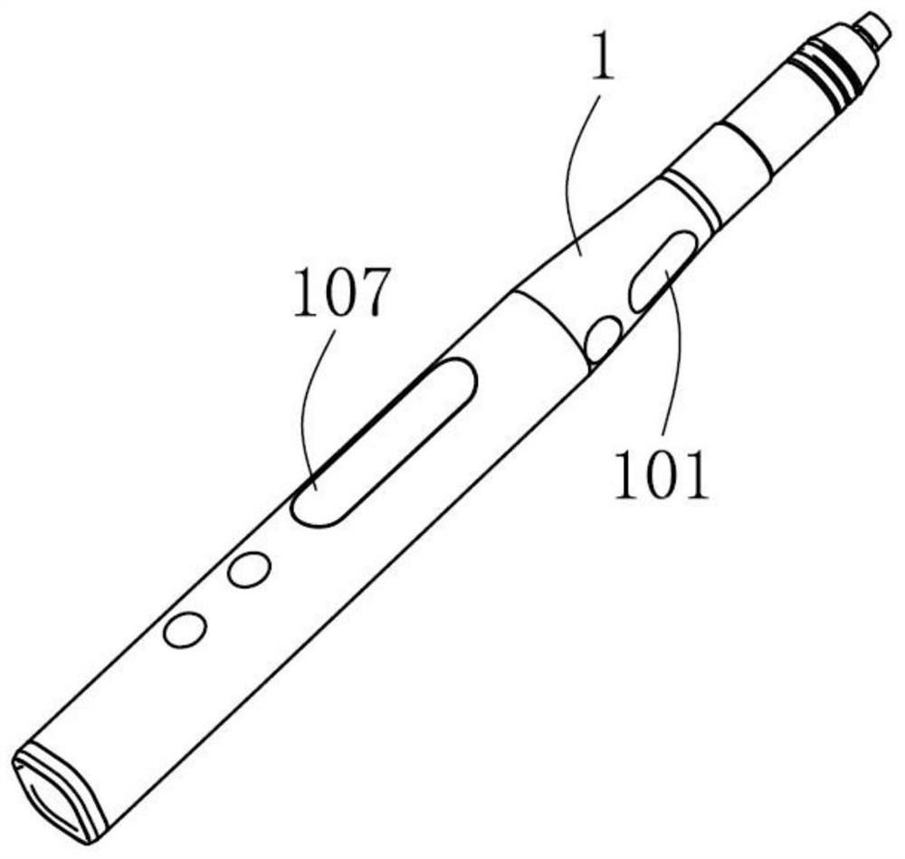
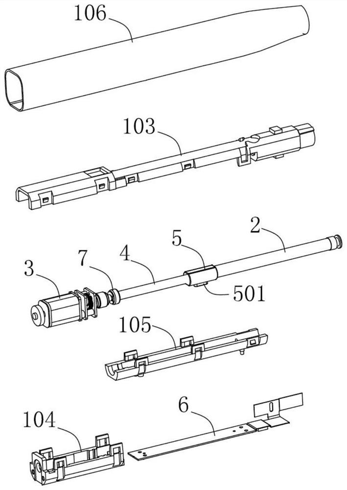
The invention relates to an oral cavity anesthesia injection device. The oral cavity anesthesia injection device comprises a shell, a push cylinder, a motor and a main control chip; the process that the main control chip controls the working state of the motor is that a trigger signal collected by a trigger signal acquisition assembly is received; when the trigger signal is received, a forward rotation control signal is sent out, and the forward rotation control signal is used for driving the motor to rotate forwards; and when the received trigger signal is interrupted, a reverse rotation control signal is sent out, and the reverse rotation control signal is used for driving the motor to rotate reversely. The trigger signal acquisition assembly is arranged on the shell, a trigger signal input by a user is acquired through the trigger signal acquisition assembly, when the trigger signal is received, the main control chip sends out the forward rotation control signal to drive the motor to rotate forward, and when the received trigger signal is interrupted, the main control chip sends out the reverse rotation control signal to drive the motor to rotate reversely. A doctor can control the whole injection process only by lifting a finger, unnecessary movement of the needle in the injection process is reduced to the maximum extent, and the position of the needle is convenient to verify.

Description

technical field [0001] The invention relates to the field of automatic control and dental equipment, relates to an oral anesthesia injection device, in particular to an oral anesthesia injection device which is convenient for verifying whether a needle is inserted into a blood vessel. Background technique [0002] Oral local anesthesia refers to the use of local anesthetic drugs to temporarily block the sensory conduction of nerve endings and fibers in a certain area of ​​the body, so that the pain in this area disappears. Before injecting the anesthetic, the doctor needs to verify the position of the needle and verify whether the needle is inserted into the blood vessel. If the needle is inserted into the blood vessel, the injection area needs to be reselected to avoid injecting the anesthetic into the blood vessel during oral local anesthesia. When using a traditional syringe for anesthesia, the verification process is to first puncture the needle into the gums according t...

Claims


Application Information

Patent Timeline
IPC IPC(8): A61M5/20A61M5/31A61M5/315A61M5/32A61M19/00
CPCA61M5/20A61M5/31511A61M5/31A61M5/32A61M19/00A61M2005/2026
Inventor 谢娟红
Owner 深圳索感科技有限公司
Learn More