Cantilever structure elastic foil dynamic pressure air floatation thrust bearing

An elastic foil and thrust bearing technology, applied in the field of foil dynamic pressure gas bearings, can solve the problems of increasing the complexity of the bearing structure, increasing the complexity of the process and the difficulty of assembly, and limiting the large-scale application in the civilian field. Reliability of start-stop, ease of frictional heat generation, inability to effectively cool down, and beneficial effect of air flow

Pending Publication Date: 2021-09-21
CHINA ELECTRONICS TECH GROUP CORP NO 16 INST
View PDF0 Cites 4 Cited by
  • Summary
  • Abstract
  • Description
  • Claims
  • Application Information

AI Technical Summary

Problems solved by technology

However, no matter whether a single top foil corresponds to multiple bottom foils or multiple top foils correspond to multiple bottom foils, the improvement of the technical solution will bring about a further increase in the complexity of the bearing structure, and the top foil and the bottom foil need to be handled separately during engineering implementation. The final fixed installation to the surface of the bearing seat greatly increases the complexity of the process and the difficulty of assembly, which limits its large-scale application in the civil field

Method used


Image

  • Cantilever structure elastic foil dynamic pressure air floatation thrust bearing
  • Cantilever structure elastic foil dynamic pressure air floatation thrust bearing
  • Cantilever structure elastic foil dynamic pressure air floatation thrust bearing

Examples


Embodiment Construction

[0029] The present invention will be further described below in conjunction with the accompanying drawings. The positional relationships such as left and right, up and down, etc. mentioned in the text are only a description of the relative relationship of the parts shown in the pictures given in the accompanying drawings, which is convenient for introduction and reference, and does not represent actual use. Time.

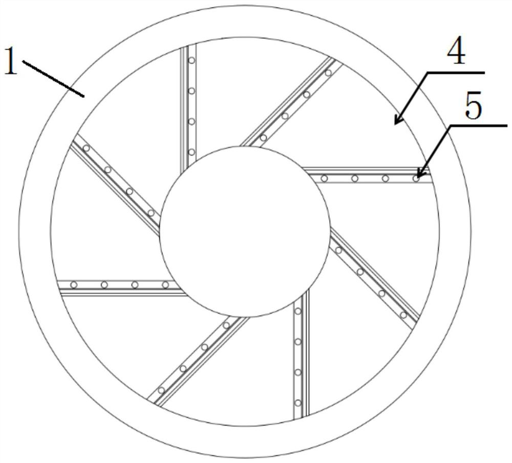
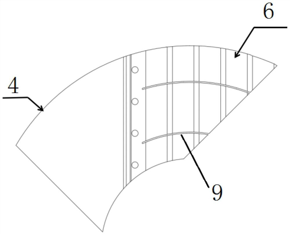
[0030] Such as Image 6As shown, the present invention provides a cantilever structure elastic foil dynamic pressure air bearing, which includes a thrust bearing housing 1 , several cantilever structure elastic foils 2 and a thrust plate 3 . The thrust bearing seat 1 is used to provide a rigid support structure for the cantilever elastic foil 2 and the thrust plate 3 . The elastic foil 2 of the cantilever structure is used for the thrust plate to provide an elastic bearing unit and a solid lubricating surface, to maintain the stability of the dynamic pressure air f...


PUM

PropertyMeasurementUnit
Thicknessaaaaaaaaaa

Abstract

The invention relates to a cantilever structure elastic foil dynamic pressure air floatation thrust bearing comprising a thrust bearing seat and a plurality of cantilever structure elastic foils installed on the thrust bearing seat. Each cantilever structure elastic foil comprises a top foil part, a bending part and a bottom foil part which are connected in sequence, and each bottom foil part is provided with a plurality of elastic units with the same height. The plurality of cantilever structure elastic foils are sequentially connected end to end, and the top foil part of each previous cantilever structure elastic foil is lapped on the elastic units of the bottom foil part of the corresponding next adjacent cantilever structure elastic foil. The air floatation thrust bearing comprises an elastic supporting unit in a bump foil bearing, has the advantages of a simple structure of a cantilever bearing, can adapt to different loads and use environments, and can meet the use requirements of high operation stability and large-scale engineering application.

Description

technical field [0001] The invention relates to the technical field of foil dynamic pressure gas bearings, in particular to an elastic foil dynamic pressure air bearing with a cantilever structure. Background technique [0002] The dynamic pressure air bearing uses the dynamic pressure effect of the gas working fluid between the friction surfaces of the bearing to lubricate and cool, and is divided into rigid surface bearings and flexible surface bearings. Compared with the rigid surface dynamic pressure gas bearing with herringbone groove or spiral groove surface, it cannot be adjusted adaptively after its nominal clearance is determined, while the biggest feature of the foil dynamic pressure gas bearing is its flexibility, which can ensure the bearing surface and support structure Deformation occurs under the effect of gas dynamic pressure, which causes changes in the gas film gap. The change of the air film gap will in turn affect the pressure distribution of the bearing...

Claims


Application Information

Patent Timeline
IPC IPC(8): F16C17/08F16C17/24F16C27/02F16C27/08F16C33/10
CPCF16C17/08F16C17/042F16C17/243F16C27/02F16C27/08F16C33/1095F16C2362/52
Inventor 绳春晨罗高乔谢洪涛高维浩刘婷满长才
Owner CHINA ELECTRONICS TECH GROUP CORP NO 16 INST
Why Eureka
Try Eureka