Boiler flue gas dry quenching system and use method

A technology for boiler flue gas and coke CDQ, which is applied in coke ovens, coke cooling, petroleum industry, etc., can solve problems such as poor coke quenching effect, high moisture content of semi-coke, and influence on product quality, so as to reduce emissions, Effects of Tapping Carbon Reduction Potential and Improving Energy Efficiency

Pending Publication Date: 2021-09-21
中煤能源研究院有限责任公司
View PDF6 Cites 0 Cited by
  • Summary
  • Abstract
  • Description
  • Claims
  • Application Information

AI Technical Summary

Problems solved by technology

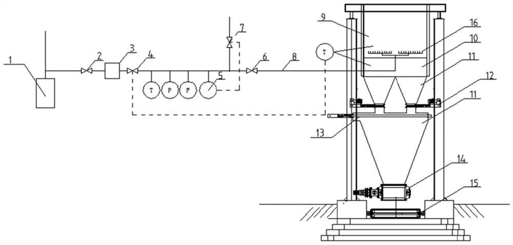
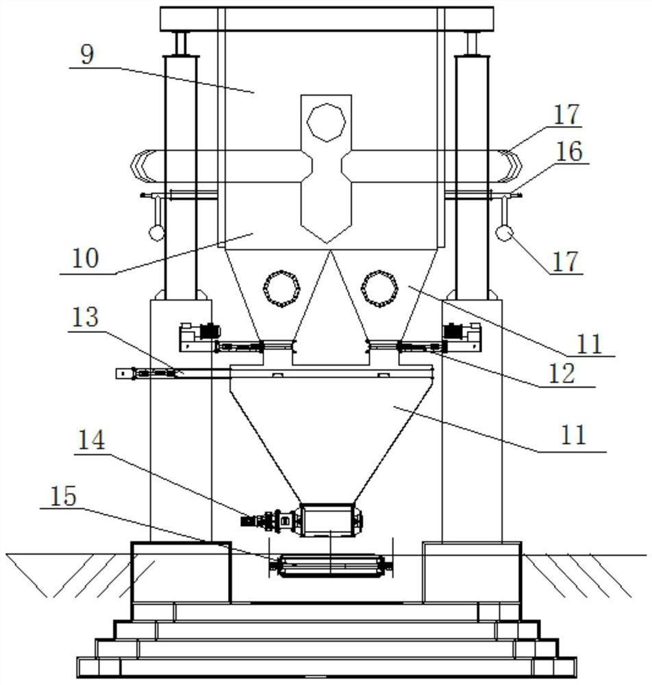
[0003] Aiming at the direct combustion drying of the semi-coke moisture in the prior art, by installing a water distribution pipe or a nozzle in the coke discharge bin, the coke quenching water is sprayed to the surface of the high-temperature semi-coke that moves down for coke quenching and cooling, and the coke quenching time is short, Moisture is in uneven contact with semi-coke, which cannot guarantee uniform coke quenching. The semi-coke is cold outside and hot inside. There are problems of high temperature, low moisture and poor sealing of the coke outlet structure. The invention provides a boiler flue gas dry Coke quenching system and usage method, the system has simple structure and convenient operation, which can effectively solve the problems existing in the prior art such as poor coke quenching effect, high semi-coke moisture affecting product quality and thermal power unit reducing carbon dioxide emissions, etc.

Method used


Image

  • Boiler flue gas dry quenching system and use method
  • Boiler flue gas dry quenching system and use method
  • Boiler flue gas dry quenching system and use method

Examples


Embodiment Construction

[0035] In order to enable those skilled in the art to better understand the solutions of the present invention, the following will clearly and completely describe the technical solutions in the embodiments of the present invention in conjunction with the drawings in the embodiments of the present invention. Obviously, the described embodiments are only It is an embodiment of a part of the present invention, but not all embodiments. Based on the embodiments of the present invention, all other embodiments obtained by persons of ordinary skill in the art without making creative efforts shall fall within the protection scope of the present invention.

[0036]It should be noted that the terms "first" and "second" in the description and claims of the present invention and the above drawings are used to distinguish similar objects, but not necessarily used to describe a specific sequence or sequence. It is to be understood that the data so used are interchangeable under appropriate c...


PUM


Abstract

The invention provides a boiler flue gas dry quenching system and a use method. Semi-coke is cooled through a gas distribution system arranged in a flue gas-semi-coke heat exchange system, a disc furnace flue gas pipeline is coiled on the side wall of the flue gas-semi-coke heat exchange system, and a plurality of nozzles are embedded in the side wall of the flue gas-semi-coke heat exchange system; and the input end of the disc furnace flue gas pipeline is connected with the output end of a flue gas pipeline in front of a furnace, the output end of the disc furnace flue gas pipeline is connected with the plurality of nozzles, and boiler flue gas is conveyed into the flue gas-semi-coke heat exchange system through the nozzles by the disc furnace flue gas pipeline, so that the boiler flue gas is in direct contact with semi-coke for heat exchange, and the semi-coke is effectively cooled. The semi-coke cooled by the boiler flue gas is secondarily cooled by a water jacket heat exchanger and extinguished by a coke discharge bin, so that effective recovery of the semi-coke is realized. The boiler flue gas is in direct contact with the semi-coke for heat exchange, the heat of the high-temperature semi-coke is absorbed, the heat enters the carbonization section to participate in carbonization reaction, the energy consumption of the carbonization furnace is reduced, and the quality of semi-coke tail gas is improved.

Description

technical field [0001] The invention relates to the technical field of low-temperature pyrolysis in coal chemical industry, in particular to a boiler flue gas CDQ system and a use method. Background technique [0002] Use Jurassic non-caking coal and weakly caking coal as raw materials to produce high-quality semi-coke, and at the same time obtain more coal tar as the target product. The basic process is: medium and low temperature-internal heating-gas heat carrier-air isolation pyrolysis process. The pyrolysis temperature is controlled at 650-750°C, and the hot semi-coke is cooled to below 260°C through a water jacket. At present, the subsequent sealing cooling and coke discharge basically adopts water sealing and sealing cooling, that is, water scooping, and the water content is generally 18-20%. If the semi-coke has too much moisture, it needs to be dried by direct combustion of gas. This process consumes energy and increases pollution. By installing water distribution...

Claims


Application Information

Patent Timeline
IPC IPC(8): C10B39/02
CPCC10B39/02
Inventor 李智锋董宝光王帅袁州李瑞华
Owner 中煤能源研究院有限责任公司
Why Eureka
Try Eureka