
Method for preparing and forming radial diffuser of large gas turbine

A radial diffuser and gas turbine technology, applied in the direction of manufacturing tools, metal processing equipment, metal processing machinery parts, etc., can solve the problems of inconvenient cooling treatment, damage to raw material clamping, tool damage, etc., to achieve stable and firm placement, Ease of processing and quality improvement

Pending Publication Date: 2021-09-21
山东优洛斯动力科技有限公司
View PDF0 Cites 0 Cited by
  • Summary
  • Abstract
  • Description
  • Claims
  • Application Information

AI Technical Summary

Problems solved by technology

[0005] Aiming at the deficiencies of the prior art, the present invention provides a preparation and molding method for a large-scale gas turbine radial diffuser, which can ensure that the diffuser can be firmly clamped during the production process, and prevents any damage during the clamping process. Clamping damage to the raw material of the diffuser is convenient for subsequent processing. During the processing of the raw material of the diffuser, the temperature can be lowered, so that the quality of the diffuser can be improved and damage to the props can be avoided. and other advantages, it solves the problem that the current device has certain defects in the production of the diffuser. It cannot clamp and fix the raw material of the diffuser firmly, and may cause clamping damage to the raw material during the clamping process; There are certain limitations in the clamping of the raw material of the diffuser; at the same time, it is not convenient to cool down during the processing of the raw material of the diffuser, which will not only reduce the quality of the diffuser, but also cause damage to the tool. question

Method used


Image

  • Method for preparing and forming radial diffuser of large gas turbine
  • Method for preparing and forming radial diffuser of large gas turbine
  • Method for preparing and forming radial diffuser of large gas turbine

Examples


Embodiment Construction

[0023] The following will clearly and completely describe the technical solutions in the embodiments of the present invention with reference to the accompanying drawings in the embodiments of the present invention. Obviously, the described embodiments are only some, not all, embodiments of the present invention. Based on the embodiments of the present invention, all other embodiments obtained by persons of ordinary skill in the art without making creative efforts belong to the protection scope of the present invention.

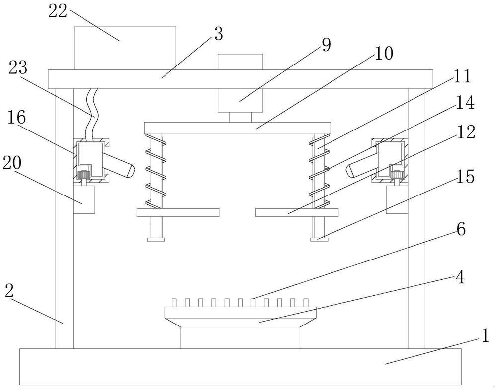
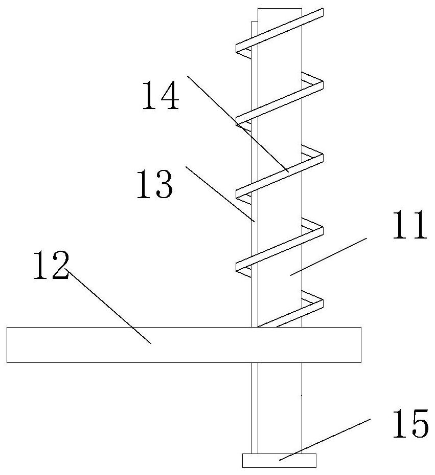
[0024] see Figure 1-4 , a preparation and molding method for a radial diffuser of a large gas turbine, comprising a mounting base 1, a mounting plate 2 is fixedly connected to both sides of the top of the mounting base 1, a support plate 3 is fixedly installed on the top of the mounting plate 2, and the mounting base 1 There is a support assembly on the top, a hydraulic cylinder 9 is fixedly installed in the middle of the support plate 3, a fixed plate 10 is ...


PUM


Abstract

The invention relates to the technical field of diffuser production, and discloses a method for preparing and forming radial diffuser of a large gas turbine. The large gas turbine comprises a mounting base, mounting plates are fixedly connected to the two sides of the top of the mounting base, a supporting plate is fixedly mounted at the tops of the mounting plates, a supporting assembly is arranged at the top of the mounting base, a hydraulic cylinder is fixedly mounted in the middle of the supporting plate, the output end of the hydraulic cylinder is fixedly connected with a fixing plate, covering and pressing assemblies are arranged on the two sides of the bottom of the fixing plate, an annular cooling assembly is arranged at one end of the mounting plate, and a cooling liquid box is fixedly mounted on one side of the top of the supporting plate. According to the manufacturing and forming method for the radial diffuser of the large gas turbine, it is guaranteed that firm clamping treatment can be conducted in the production process of the diffuser, clamping damage to raw materials of the diffuser can be completely eradicated in the clamping process, cooling treatment can be conducted in the machining treatment process of the raw materials of the diffuser, therefore, the quality of the diffuser can be improved, and damage to tools is also avoided.

Description

technical field [0001] The invention relates to the technical field of diffuser production, in particular to a preparation and molding method for a radial diffuser of a large gas turbine. Background technique [0002] The diffuser is produced by a centrifugal compressor and relies on kinetic energy to convert static pressure energy. The absolute velocity C2 of the airflow at the impeller outlet of the centrifugal compressor is generally 200-300m / s. The air velocity of the impeller of the high-energy head can reach more than 500m / s. This part of kinetic energy accounts for a considerable proportion of the total energy head given to the gas by the impeller. For example, the radial straight blade type impeller accounts for 50%, and the water pump type and compressor type impeller also account for 25%-40%. Therefore, this part of kinetic energy must be effectively converted into static pressure energy, which is the task of the diffuser. The diffuser also plays the role of col...

Claims


Application Information

Patent Timeline
IPC IPC(8): B23D79/00B23Q3/00B23Q11/10
CPCB23D79/00B23Q3/00B23Q11/10
Inventor 贺子淼杨晓辉
Owner 山东优洛斯动力科技有限公司
Learn More