
An optical glass processing fixture

A technology for fixing devices and optical glass, which is applied in the direction of workpiece clamping devices, workbenches, manufacturing tools, etc., can solve the problems of few supporting contact parts, cracking and breaking of optical glass parts, material waste, etc., and achieve the purpose of strengthening evenly distributed support, Avoid cracked or shattered effects

Active Publication Date: 2021-10-26
江苏圣锦硅业新材料有限公司
View PDF0 Cites 0 Cited by
  • Summary
  • Abstract
  • Description
  • Claims
  • Application Information

AI Technical Summary

Problems solved by technology

[0003] In the processing and manufacturing process of optical glass, fixing the optical glass to facilitate processing, and realizing positioning by fixing is a common processing method in the processing of optical glass. The invention provides a fixing device for processing optical glass, which is used for processing Fixed and clamped positioning of optical glass, especially suitable for such as Figure 8 The optical glass with circular structure and spherical surface is processed and fixed, and the existing fixing device is used for such as Figure 8 When the optical glass piece shown is fixed and clamped, usually only the edge position of the optical glass piece is supported and clamped, but the entire spherical surface part of the optical glass piece is not supported effectively, and there are too few supporting contact parts, so in In the actual processing process, it is easy to cause the entire piece of optical glass to break and break due to improper operation, resulting in waste of materials

Method used


Image

  • An optical glass processing fixture
  • An optical glass processing fixture
  • An optical glass processing fixture

Examples


Embodiment Construction

[0023] The specific embodiment of the present invention will be described in further detail by describing the embodiments below with reference to the accompanying drawings, the purpose is to help those skilled in the art to have a more complete, accurate and in-depth understanding of the concept and technical solutions of the present invention, and To facilitate its practice, but not as a limitation of the invention.

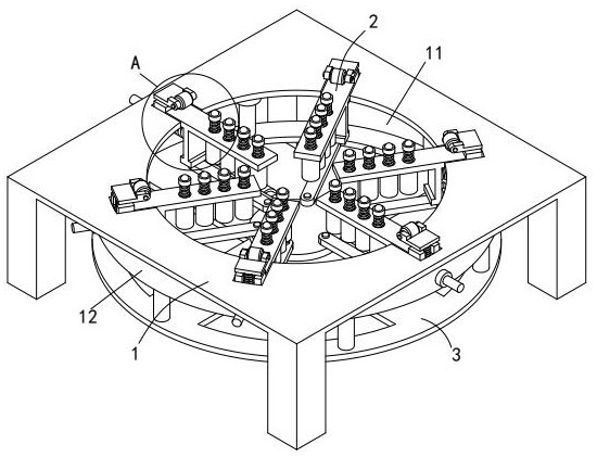
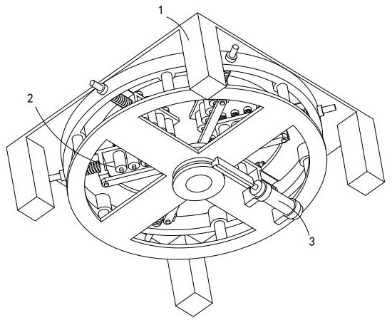
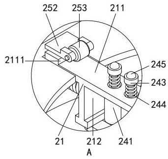
[0024] Such as figure 1 , figure 2 and Figure 4 As shown, a fixing device for optical glass processing includes a fixed table 1, a round frame hole 11 is arranged on the table surface of the fixed table 1, and a guide ring 12 coaxial with the round frame hole 11 is arranged on the bottom end of the table surface of the fixed table 1, and the circle The frame hole 11 is provided with six clamping and positioning components 2 distributed around the circumference of its central axis; each clamping and positioning component 2 is slidingly fitted with the guide ...


PUM


Abstract

The invention relates to the technical field of glass processing, in particular to a fixing device for optical glass processing, comprising a fixing table, a round frame hole is arranged on the table top of the fixing table, and a round frame hole is arranged at the bottom end of the table top of the fixing table. A coaxial guide ring, the circular frame hole is provided with six clamping and positioning components distributed around the circumference of its central axis; each of the clamping and positioning components is slidably fitted with the guide ring; the bottom of the guide ring The end is provided with a clamping drive mechanism that drives the six clamping and positioning components to slide synchronously; compared with the prior art, the device provided by the present invention changes the traditional fixing device in processing optical glass with a spherical curved surface of a circular structure. When only clamping and supporting the edge is performed, the evenly distributed support for the entire spherical surface is strengthened, thereby greatly reducing the problems caused by improper processing operations due to too few clamping and supporting contact parts of optical glass in the prior art. The probability of the problem causing the optical glass to crack or shatter.

Description

technical field [0001] The invention relates to the technical field of glass processing, and specifically provides a fixing device for optical glass processing. Background technique [0002] Optical glass refers to glass that can change the direction of light propagation and change the relative spectral distribution of ultraviolet, visible or infrared light when assembled in optical instruments; optical glass in the narrow sense refers to colorless optical glass; optical glass in the broad sense also includes Colored optical glass, laser glass, quartz optical glass, anti-radiation glass, ultraviolet infrared optical glass, fiber optical glass, acousto-optic glass, magneto-optical glass and photochromic glass; optical glass can be used to manufacture lenses, prisms and mirrors in optical instruments And windows, etc., components made of optical glass are key components in optical instruments. [0003] In the processing and manufacturing process of optical glass, fixing the o...

Claims


Application Information

Patent Timeline
Patent Type & Authority Patents(China)
IPC IPC(8): B25B11/00B25H1/08
CPCB25B11/00B25H1/08
Inventor 李超
Owner 江苏圣锦硅业新材料有限公司
Learn More